
Diesel engine exhaust gas purification muffler

A diesel engine and exhaust gas purification technology, applied in engine components, machines/engines, mufflers, etc., can solve the problems of inability to transform diesel engines, poor decomposition effect, high oxygen content in exhaust gas, and achieve poor exhaust gas and good purification effect. , the effect of low price

Inactive Publication Date: 2015-10-07
汪荣林
View PDF8 Cites 0 Cited by
  • Summary
  • Abstract
  • Description
  • Claims
  • Application Information

AI Technical Summary

Problems solved by technology

Due to the high operating temperature of diesel engines, there are more nitrogen oxides in the exhaust gas, and the exhaust gas contains high oxygen at low speeds, and the three-way catalysis has a poor decomposition effect on nitrogen oxides; exhaust gas recirculation technology and urea SCR catalytic technology, not only the cost High, technically difficult, and unable to transform existing diesel engines

Method used

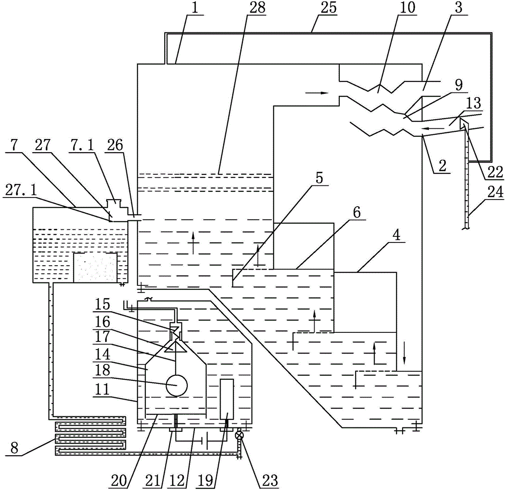

Image

  • Diesel engine exhaust gas purification muffler
  • Diesel engine exhaust gas purification muffler

Examples


no. 1 example

[0018] see figure 1 , a diesel engine exhaust gas purification muffler, comprising a purification muffler main body 1, an electrolytic tank with a water pump 23, a heat dissipation pipe 8, and a water storage tank 7, and the purification muffler main body 1 includes two air intake chambers and a purification chamber formed by partitions 4 The chamber body, wherein the purification chamber is provided with a combined structure of several gas baffles 5 and porous plates 6 to form a stepped purification channel above two levels; One end of air outlet pipe 10 is communicated with purification chamber, and the other end is communicated with air outlet 3, and one end of spiral air inlet pipe 9 is communicated with air inlet 2, and the other end communicates with air inlet chamber in the air inlet chamber, and air inlet 2 is externally connected with a Air intake pipe 13, straight air intake pipe 13 is provided with a conical nozzle 22 with an opening inward, the nozzle 22 is connect...

no. 2 example

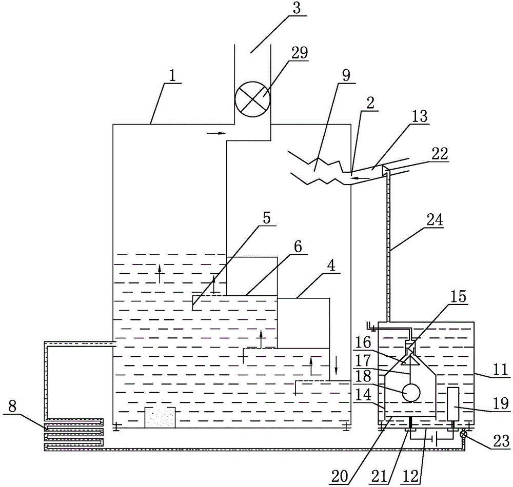
[0027] join figure 2 , this embodiment is used for wet desulfurization and nitrogen removal of industrial boilers. The difference from the first embodiment is that the spiral air outlet pipe 10 is changed to a blower 29, the water storage tank 7 is reduced, and the electrolytic tank is arranged at the air inlet. 2 below. Other parts not described are the same as the first embodiment.


PUM


Abstract

The invention provides an exhaust purification silencer of a diesel engine. The exhaust purification silencer comprises a purification silencer body, a gas inlet of the purification silencer body, a gas outlet of the purification silencer body, a water tank, an electrolytic box with a water pump, and a radiating tube. The exhaust purification silencer is characterized in that the purification silencer body comprises a gas inlet cavity and a purification cavity, and the gas inlet cavity and the purification cavity are formed through separation of partition boards. A spiral gas inlet pipe and a spiral gas outlet pipe are arranged in the gas inlet cavity in a mutually twining mode. One end of the spiral gas outlet pipe is communicated with the purification cavity, and the other end of the spiral gas outlet pipe is communicated with the gas outlet. One end of the spiral gas inlet pipe is communicated with the gas inlet, and the other end of the spiral gas inlet pipe is communicated with the gas inlet cavity in the gas inlet cavity. A plurality of combined structures formed by gas baffle plates and perforated plates are arranged in the purification cavity so as to form a stepped purification channel with more than two steps. The exhaust purification silencer of the diesel engine is provided with the gas inlet cavity with large space, and the large space of the gas inlet cavity can buffer airflow pulse impact; waste gas can be purified in a small box body through multi-step similar effects; especially, when the same stepped purification channel is used for wet-type sulfur removal and wet-type nitrogen removal in a boiler, a channel with more than five steps can be arranged.

Description

technical field [0001] The invention relates to a diesel engine exhaust gas purification muffler, which is mainly used in diesel engine exhaust gas purification and muffler. Background technique [0002] At present, with the continuous improvement of living standards, diesel engines are used more and more due to their good economic performance. The exhaust gas produced by diesel engines is becoming more and more serious in air pollution, especially the pollution of nitrogen oxides in the exhaust gas. Due to the high operating temperature of diesel engines, there are more nitrogen oxides in the exhaust gas, and the exhaust gas contains high oxygen at low speeds, and the three-way catalysis has a poor decomposition effect on nitrogen oxides; exhaust gas recirculation technology and urea SCR catalytic technology, not only the cost High, technically difficult, and unable to transform existing diesel engines. At present, there is an urgent need for a diesel engine exhaust gas pu...

Claims


Application Information

Patent Timeline
Patent Type & Authority Patents(China)
IPC IPC(8): F01N3/08F01N1/08
Inventor 汪荣林
Owner 汪荣林
Learn More