Method for forming front electrode of solar cell

A technology of solar cells and front electrodes, applied in the direction of copying/marking methods, circuits, photovoltaic power generation, etc., can solve the problems of semiconductor layer damage, nozzle clogging, resistance increase, etc., and achieve the effect of reducing the electrode width and increasing the amount of light

Inactive Publication Date: 2014-01-01
NJETTE
View PDF5 Cites 3 Cited by
  • Summary
  • Abstract
  • Description
  • Claims
  • Application Information

AI Technical Summary

Problems solved by technology

[0008] However, in the solar cell of the prior art, the front electrode is formed by printing an electrode solution having a viscosity of 30,000 cp to 150,000 cp by a contact printing method such as screen printing, so there is a limit to reducing the electrode width w of the front electrode.
[0009] In addition, the amount of charge moving through the front electrode is proportional to the cross-sectional area of ​​the front electrode (the product of the electrode width w and the electrode height h), so if only the electrode width w is reduced at the same electrode height h as in the past, the The problem of increased resistance
[0010] Moreover, as the semiconductor layer of solar cells continues to become thinner, if contact printing methods such as screen printing are used, there will be a problem of damage to the semiconductor layer during the execution of the process. Therefore, a method for ejecting ink through nozzles is needed. Non-contact printing methods such as inkjet
[0011] In addition, the maximum viscosity of the electrode solution ejected by piezoelectric inkjet or pyroelectric inkjet is about 30cP, so there is a limitation when printing the electrode solution with the viscosity (30000cp to 150000cp)
[0012] Also, in the conventional inkjet method, although the size of the solid particles contained in the electrode solution is nanoscale, there are also problems such as nozzle clogging.
Here, in order to prevent clogging of the nozzle, the diameter of the nozzle can be enlarged. However, in the conventional inkjet device, if the diameter of the nozzle is enlarged, it is difficult to realize the desired fine electrode width w

Method used


Image

  • Method for forming front electrode of solar cell
  • Method for forming front electrode of solar cell
  • Method for forming front electrode of solar cell

Examples


Embodiment Construction

[0049] Before the description, it should be emphasized that in multiple embodiments, the same reference numerals are used for components with the same structure, and a representative description is made in the first embodiment, and the description in other embodiments is Different structure from the first embodiment.

[0050] Hereinafter, a method for forming a front electrode of a solar cell according to an embodiment of the present invention will be described in detail with reference to the drawings.

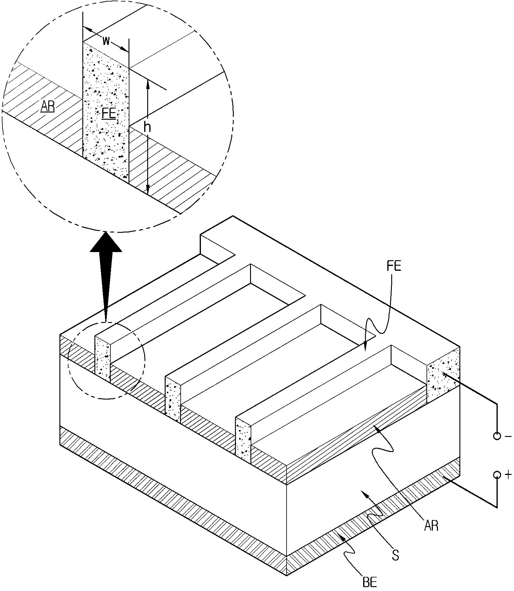
[0051] Such as figure 1 As shown, the solar cell is formed with a semiconductor layer S formed by forming an n-type semiconductor layer on the front side of a silicon substrate and a p-type semiconductor layer on the back side so as to include a pn junction interface. After coating the front surface of the semiconductor layer S with an anti-reflection film AR for minimizing reflection of light incident on the solar cell, a front electrode FE contacting the semiconductor layer...


PUM


Abstract

The method for forming a front electrode of a solar cell according to the present invention relates to a process whereby a front electrode is formed on the surface of a semiconductor layer of a solar cell. The method for forming a front electrode on the front surface of the semiconductor layer of a solar cell, comprises the steps of: printing an electrode solution on the front surface of the semiconductor layer for forming the electrode; and hardening said electrode solution such that said electrode solution printed on said semiconductor layer by said electrode-forming step configures said front electrode. Said electrode solution is formed by mixing a bonding agent for bonding said semiconductor layer and said metal, and the metal for forming said front electrode. Said electrode-forming step provides an electric charge to said electrode solution by means of the electric energy applied by one or more electrohydrodynamic (EHD) inkjet printing operations, and discharges said electrically-charged electrode solution from a nozzle by means of an electrostatic force.

Description

technical field [0001] The present invention relates to a method for forming a front electrode of a solar cell, and in more detail relates to a method for forming a front electrode of a solar cell as follows: printing an etching solution in the step of etching an antireflection film, or printing for forming For the electrode solution or conductive solution of the front electrode, the solution is printed by electrohydrodynamic (EHD, Electrohydrodynamic) inkjet method (Ink Jetting Type), thereby reducing the width of the front electrode printed on the semiconductor layer of the solar cell, thereby enabling Provides a high aspect ratio front electrode and can increase the amount of light incident to the solar cell. Background technique [0002] Recently, in response to the continuous rise in international oil prices and the depletion of fossil fuels, there has been an increasing need to discover alternative energy resources. At the same time, with the entry into force of the c...

Claims


Application Information

Patent Timeline
Patent Type & Authority Applications(China)
IPC IPC(8): H01L31/18B41M5/00B41M1/26
CPCY02E10/52H01L31/022425H01L31/02168Y02E10/50H01L31/0224H01L31/04H01L31/18
Inventor 边渡泳
Owner NJETTE
Why Eureka
Try Eureka