
System and method for testing GIS electronic transformer

A technology of electronic transformer and testing system, which is applied in the direction of transformer testing, instrumentation, measuring electricity, etc., and can solve problems such as electromagnetic protection failure, electronic transformer being susceptible to interference, and being susceptible to interference

Active Publication Date: 2014-01-01
STATE GRID CORP OF CHINA +2
View PDF5 Cites 26 Cited by
  • Summary
  • Abstract
  • Description
  • Claims
  • Application Information

AI Technical Summary

Problems solved by technology

[0004] From the types and characteristics of common electromagnetic interference in substations and its interference coupling path to electronic transformers, it can be seen that in the substation environment, the reason why electronic transformers are susceptible to interference is mainly because their equipment is closer to the primary circuit. , Under the condition of system short circuit, it is more susceptible to interference through direct conduction and electromagnetic field coupling, and its layout, merging unit and its power supply module are also very easy to cause interference through electromagnetic radiation or ground potential rise
The intensity of these interferences far exceeds the interference level specified in the current electromagnetic compatibility standards, which is also the main reason why the electronic transformer has passed the electromagnetic compatibility test and the electromagnetic protection failure occurs on site.

Method used


Image

  • System and method for testing GIS electronic transformer
  • System and method for testing GIS electronic transformer
  • System and method for testing GIS electronic transformer

Examples


Embodiment 1

[0050] In this embodiment, a 220KV GIS pipeline is taken as an example to introduce a GIS electronic transformer testing system. See attached Figure 1-3 , respectively disclose a 220KV GIS pipeline installation dimension diagram, a test circuit diagram and a test layout diagram according to the present invention.

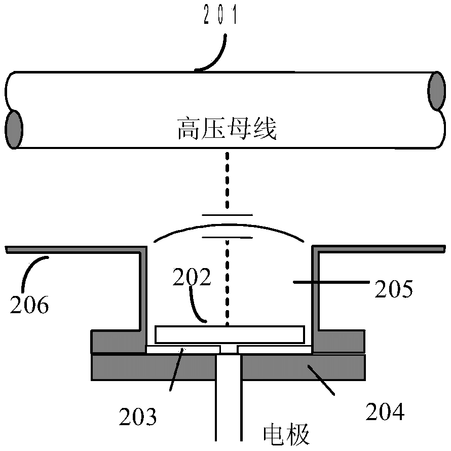
[0051] The GIS electronic transformer testing system includes two BSG bushings, with a GIS pipeline between the two BSG bushings, one of which is a power bushing 105, and the power bushing is connected to each other in parallel with the high voltage test The transformer U1 and the capacitive voltage divider C1 for protecting the power supply, the capacitive voltage divider C1 is used to reduce the resonance effect caused by the higher power supply impedance, the other bushing is the load bushing 106, and the load The bushing is connected to the load capacitor C2. Since all GIS electronic transformers are based on the principle of capacitive voltage division with s...

Embodiment 2

[0072] The electromagnetic compatibility of the electronic transformer is tested by using the isolating switch to open and close the capacitive small current. The basic principle is to test the electromagnetic compatibility of the electronic transformer under the condition of strong electromagnetic interference. Therefore, the parameters of the strong electromagnetic interference condition are important for the test. one of the parameters. The main parameters of the process of separating and closing capacitive small currents of the isolating switch are: voltage, current, electric field, magnetic field, and shell potential rise. Among them, voltage and current are the most important parameters, so measuring voltage and current is a key step in the immunity test of the electronic transformer under the condition of opening and closing capacitive small current of the disconnector.

[0073] See attached image 3 , taking 220KV as an example, which includes a first calibration primar...

Embodiment 3

[0083] This embodiment discloses a testing method using the GIS electronic transformer testing system based on Embodiments 1 and 2.

[0084] 1. According to Figure 1-3 Build a GIS-type electronic transformer test system based on an isolating switch;

[0085] 2. Ensure that the merging unit 111 is placed in the sink cabinet, that the merging unit is running normally with electricity, and that the communication with the fault recorder 112 is normal;

[0086] 3. Close the second isolating switch DS2, the first isolating switch DS1 is in the opening state, and the output voltage of the high-voltage test transformer is raised to Where Um is the highest line voltage;

[0087] 4. Close the first isolating switch, record the test data 101, 104 of the primary transient test system and the secondary fault recording data;

[0088] 5. Turn on the first isolation switch DS1 after an interval of 2 minutes, and record the test data 101, 104 of the primary transient test system and the s...


PUM


Abstract

The invention discloses a system for testing a GIS electronic transformer based on a small connecting and disconnecting capacity current of a disconnecting switch. The system comprises a high-voltage testing transformer connected to a BSG sleeve, a capacitive voltage divider, a load capacitor arranged on the other BSG sleeve, the disconnecting switch arranged between the two sleeves, a calibration primary transient state testing system and the electronic transformer to be tested, one end of a secondary converter is connected with the electronic transformer to be tested, the other end of the secondary converter is connected with a merging unit, and the other end of the merging unit is connected with a fault recorder. When the disconnecting switch is connected or disconnected, voltage values and current values of a high-voltage bus are tested and compared with the output values of the electronic transformer to be tested. According to the testing system, the electromagnetic environment at the voltage levels of 110KV, 220KV, 500KV and the like in the process of electricity connection and electricity disconnection can be simulated, the site disconnecting switch connecting and disconnecting hollow conducting wire and capacity small current loading process is simulated, similar site transient sate strong-interference is generated, and the electromagnetic protective performance of the electronic transformer under the condition is examined.

Description

technical field [0001] The invention relates to a GIS electronic transformer testing system and a method thereof, in particular to a GIS electronic transformer testing system and a testing method based on an isolating switch for separating and closing capacitive small currents. Background technique [0002] With the construction of the smart grid, electronic transformers are widely used in the smart grid. The strategic goal of "building a unified and strong smart grid" proposed by the State Grid Corporation of China's scientific and technological development plan has put forward higher requirements for the quality and performance of electronic transformer products, and the reliability, stability and accuracy of product operation. Among them, electromagnetic interference is an important factor affecting the reliability and stability of electronic transformers. [0003] At present, the detection understanding of EMC of electronic transformers at home and abroad is still based...

Claims


Application Information

Patent Timeline
Patent Type & Authority Applications(China)
IPC IPC(8): G01R35/02G01R31/62
CPCG01R31/3274G01R31/62
Inventor 张勤叶国雄郭克勤刘彬黄华童悦刘翔胡蓓万罡冯翔翔邬文亮陈鹏杨帆邓小聘王焱王晓周代静汪英英熊俊军刘勇
Owner STATE GRID CORP OF CHINA
Learn More