Wire clamp special for testing of transformer

A technology for transformers and wire clamps, which is applied in the field of special wire clamps for transformer testing, can solve problems such as inaccurate test data, and achieve the effects of ensuring test safety, convenient installation, and simple structure

Active Publication Date: 2014-01-01
STATE GRID CORP OF CHINA +1
View PDF4 Cites 12 Cited by
  • Summary
  • Abstract
  • Description
  • Claims
  • Application Information

AI Technical Summary

Problems solved by technology

[0003] Due to the limitation of the opening and thickness, the measuring wire clip of the existing transformer DC resistance tester cannot be directly clamped on the lead-out cable head of the transformer, but can only be clamped on the wiring board for measurement. Due to various external factors, the test data is inaccurate

Method used


Image

  • Wire clamp special for testing of transformer
  • Wire clamp special for testing of transformer
  • Wire clamp special for testing of transformer

Examples


Embodiment Construction

[0018] The embodiments of the present invention will be described in further detail below in conjunction with the accompanying drawings. It should be emphasized that the following embodiments are illustrative, not restrictive, and should not be used as limitations of the present invention.

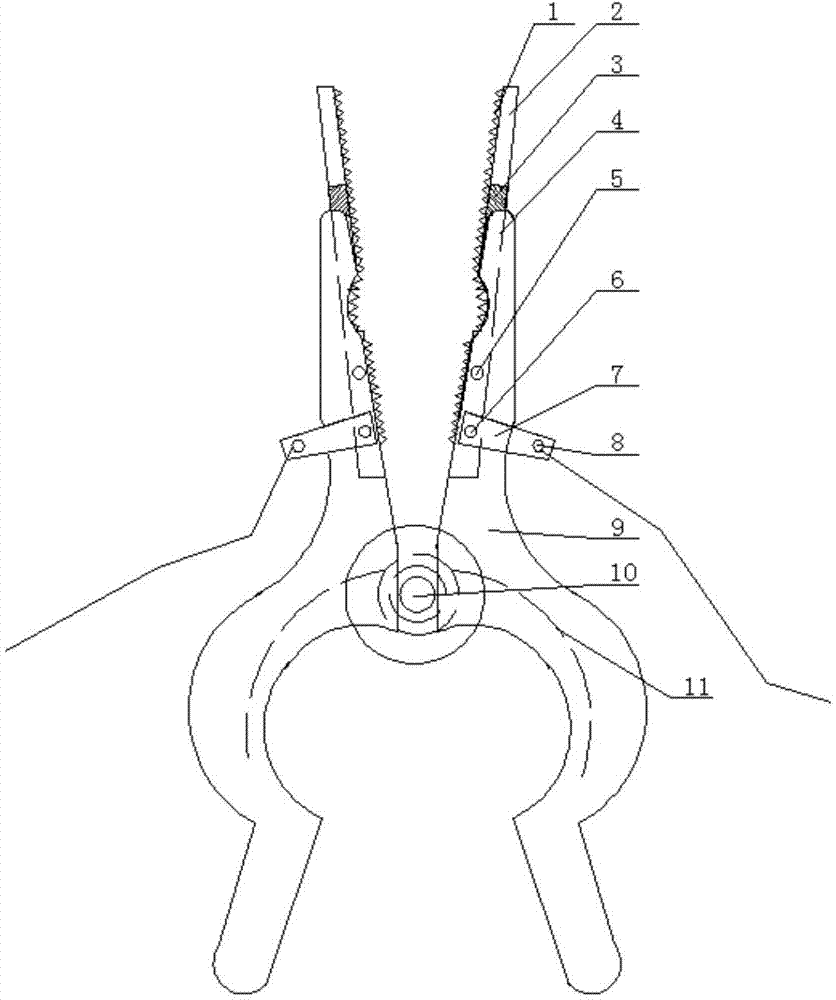
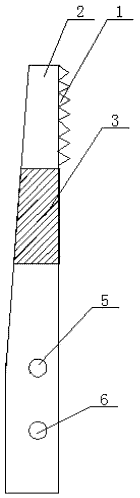
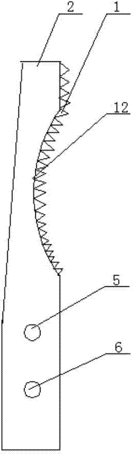
[0019] A special clamp for transformer testing, such as figure 1 As shown, two wire clip bodies 9 that are left and right symmetrical are included, and the two wire clip bodies are fixed by the threading bolts 10, and the two thread clip bodies are rotated around the threading bolts by the springs 11 mounted on the bolts, the innovation of the present invention The point is that there are installation grooves 4 on the inner sides of the chuck ends of the two clamp bodies, and clip fixing holes 5 and lug fixing holes 6 are formed on the lower part of the installation grooves. The fitting structures in the two installation grooves are the same There are two kinds of special clips, one is a s...


PUM


Abstract

The invention relates to a wire clamp special for testing of a transformer. The wire clamp comprises two wire clamp bodies, a bolt penetrating through the two wire clamp bodies and fixing the two wire clamp bodies, and a spring. Installation grooves are respectively formed in the inner sides of the clamping head ends of the two wire clamp bodies. Clamping piece fixing holes and wiring piece fixing holes are formed in the lower portions of the installation grooves. Transformer direct current resistance testing specialized clamping pieces of the same structure or transformer breaker loop resistance testing specialized clamping pieces of the same structure are respectively assembled in the two installation grooves and are fixed in the installation grooves through the clamping piece fixing holes and the wiring piece fixing holes. The wiring piece fixing holes fix wiring pieces at the same time, and wiring screws on the wiring pieces are fixedly connected with wires. By adopting a split structure, the wire clamp is simple in structure and convenient to install, and can improve the accuracy of test data, shorten the test time and lower the misjudgment probability after being used.

Description

technical field [0001] The invention belongs to auxiliary equipment of electric power testing instruments, and in particular relates to a special line clamp for transformer testing. Background technique [0002] In the operation of power equipment, the transformer DC resistance test is a simple and important test item in the transformer test. Testing the DC resistance of the transformer winding together with the bushing can check the welding quality of the wire joint inside the winding, the welding quality of the lead wire and the winding joint, whether the tap position of the voltage tap changer and the contact between the lead wire and the bushing are good, and whether the parallel branch connection is good. Whether it is correct, whether the current-carrying part of the transformer is open circuit, poor contact, and whether the winding is open circuit. [0003] Due to the limitation of the opening and thickness, the measuring clamp of the existing DC resistance tester fo...

Claims


Application Information

Patent Timeline
Patent Type & Authority Applications(China)
IPC IPC(8): G01R1/06G01R31/02
Inventor 张威庞博赵婧孟繁喜吕绍杰
Owner STATE GRID CORP OF CHINA
Why Eureka
Try Eureka