Electric device temperature monitoring system

A technology for monitoring systems and electrical appliances, applied to thermometers, thermometers with physical/chemical changes, instruments, etc., can solve problems such as high cost, low monitoring accuracy, and poor anti-interference performance, and achieve simple structure, high monitoring accuracy, The effect of anti-electromagnetic interference

Inactive Publication Date: 2014-01-01
常熟市明阳电器安装工程有限公司
View PDF3 Cites 3 Cited by
  • Summary
  • Abstract
  • Description
  • Claims
  • Application Information

AI Technical Summary

Problems solved by technology

At present, the common monitoring system is relatively complex, with high cost, poor anti-interference performance and low monitoring accuracy.

Method used


Image

  • Electric device temperature monitoring system

Examples


Embodiment Construction

[0011] The following will clearly and completely describe the technical solutions in the embodiments of the present invention. Obviously, the described embodiments are only some of the embodiments of the present invention, rather than all the embodiments. Based on the embodiments of the present invention, all other embodiments obtained by persons of ordinary skill in the art without making creative efforts belong to the protection scope of the present invention.

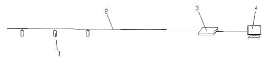
[0012] see figure 1 , the electrical appliance temperature monitoring system of the present invention comprises a plurality of optical fiber temperature sensors 1, an optical fiber demodulator 3 and a monitoring computer 4, and the plurality of optical fiber temperature sensors 1 and the optical fiber demodulator 3 are all connected in series through a transmission cable 2, and the The optical fiber demodulator 3 is connected with the monitoring computer 4 for electrical signals.

[0013] Further, a plurality of opt...


PUM


Abstract

The invention discloses an electric device temperature monitoring system which comprises a plurality of optical fiber temperature sensors, an optical fiber demodulator and a monitoring computer. The optical fiber temperature sensors and the optical fiber demodulator are connected in series through transmission optical cables and the optical fiber demodulator is connected with the monitoring computer through electric signals. According to the mode, the electric device temperature monitoring system can conduct accurate temperature monitoring on an operated electric device and is simple in structure, resistant to electromagnetic interference and high in monitoring accuracy.

Description

technical field [0001] The invention relates to an electrical appliance temperature monitoring system, which is used for temperature monitoring of working electrical appliances. Background technique [0002] When some important electrical appliances are working, they are more sensitive to temperature changes, and it is necessary to monitor the temperature of the working electrical appliances and deal with them in time. At present, common monitoring systems are relatively complex, with high cost, poor anti-interference performance, and low monitoring accuracy. Contents of the invention [0003] The technical problem mainly solved by the present invention is to provide an electrical appliance temperature monitoring system, which can accurately monitor the temperature of working electrical appliances, has a simple structure, is resistant to electromagnetic interference, and has high monitoring accuracy. [0004] In order to solve the above-mentioned technical problems, the t...

Claims


Application Information

Patent Timeline
Patent Type & Authority Applications(China)
IPC IPC(8): G01K11/32
Inventor 王勤庚
Owner 常熟市明阳电器安装工程有限公司
Why Eureka
Try Eureka