
Two-way inflation pump

A technology of air pump and one-way air intake valve, which is applied in the direction of pumps, pump components, variable capacity pump components, etc., can solve the problems of poor use efficiency and inability to perform inflation, and achieve high use efficiency and ingenious design Effect

Inactive Publication Date: 2014-01-01
JUNHONG PLASTIC PROD CO LTD
View PDF8 Cites 6 Cited by
  • Summary
  • Abstract
  • Description
  • Claims
  • Application Information

AI Technical Summary

Problems solved by technology

[0002] There are quite a few types of air pumps that are operated by the user's hands. The most typical traditional structure is the air pump used by ordinary people to inflate bicycle tires, commonly known as an air pump. This air pump has a cylindrical body. A piston operated by the action rod is assembled in the middle, and a handle is provided on the top of the action rod for the user to hold, and an inflatable tube is extended from the lower end of the body, and a piston is arranged at an appropriate position of the body. When the user pulls up the handle , the air will enter under the piston inside the body, and when the user presses the handle down, the piston will push the air in the body into the inflatable tube, and the inflatable tube will provide an inflation effect. This traditional The air pump of the type is a one-way air pump, that is, it can only provide inflation in a single stroke of downward movement during a round-trip stroke of the piston moving up and down, and cannot perform inflation in the stroke of upward movement. Therefore, it is not efficient to use

Method used


Image

  • Two-way inflation pump
  • Two-way inflation pump
  • Two-way inflation pump

Examples


Embodiment Construction

[0030] The present invention will be described in further detail below in conjunction with the accompanying drawings.

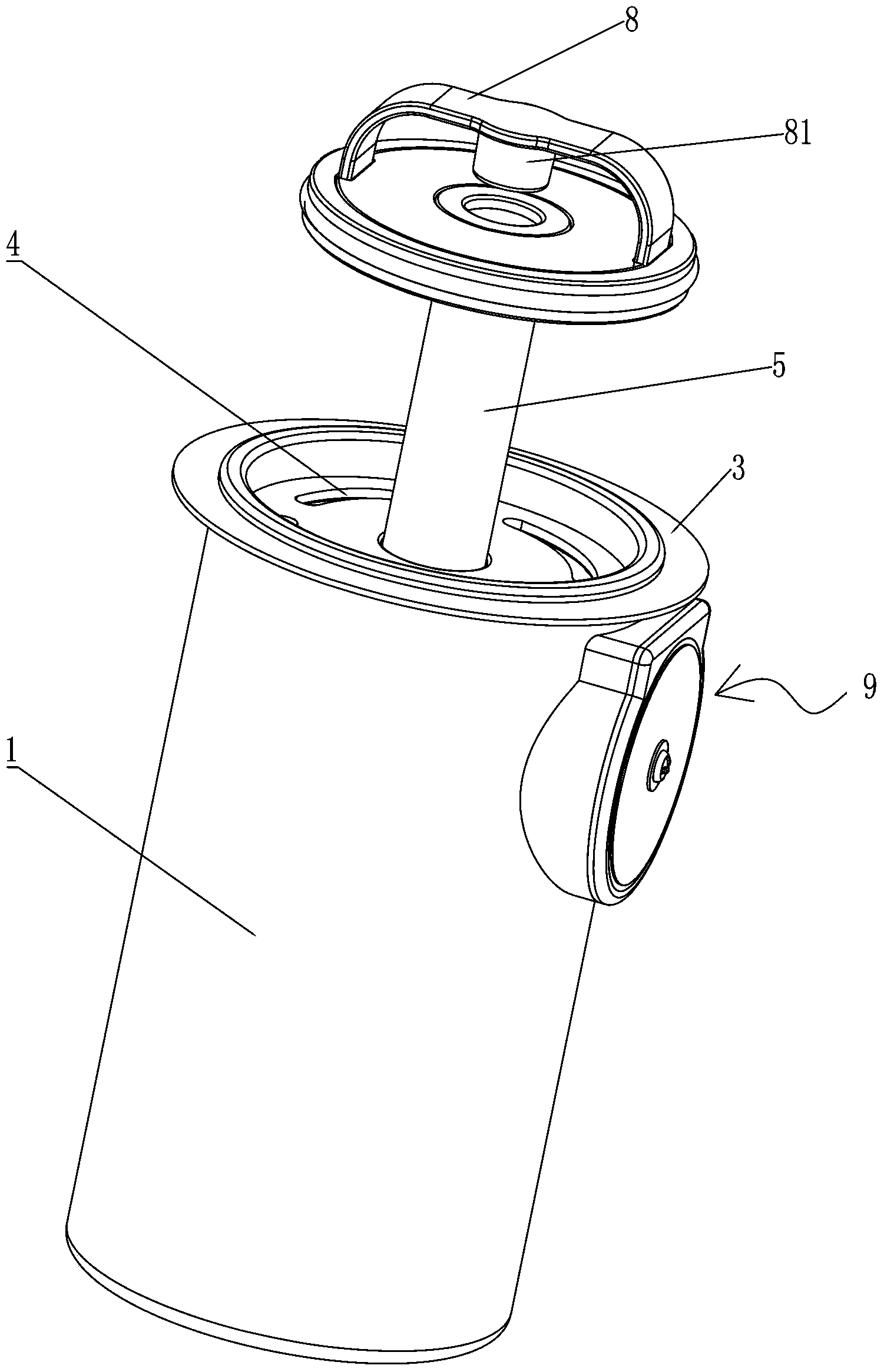
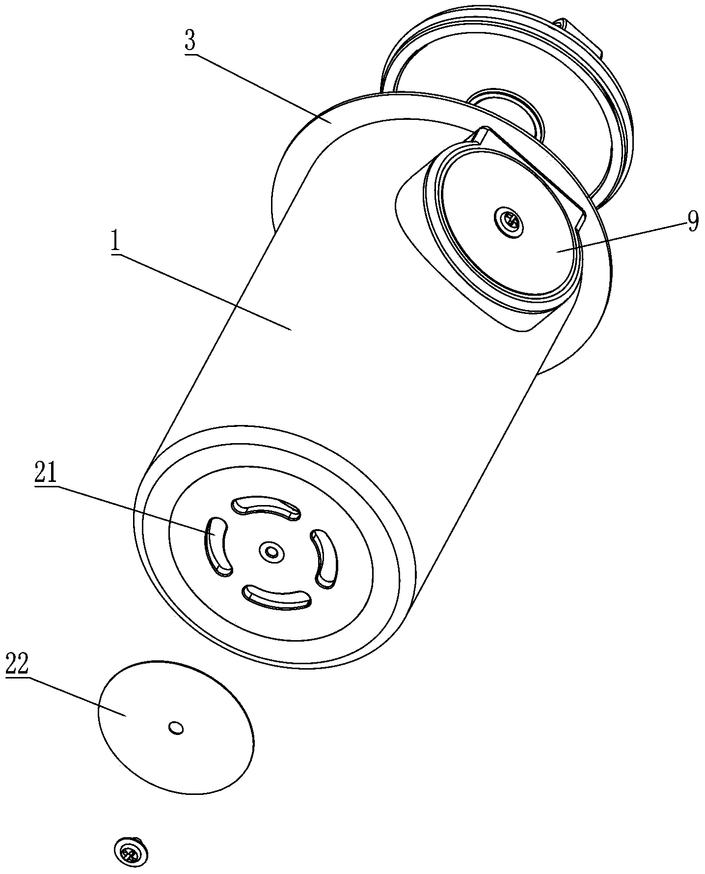
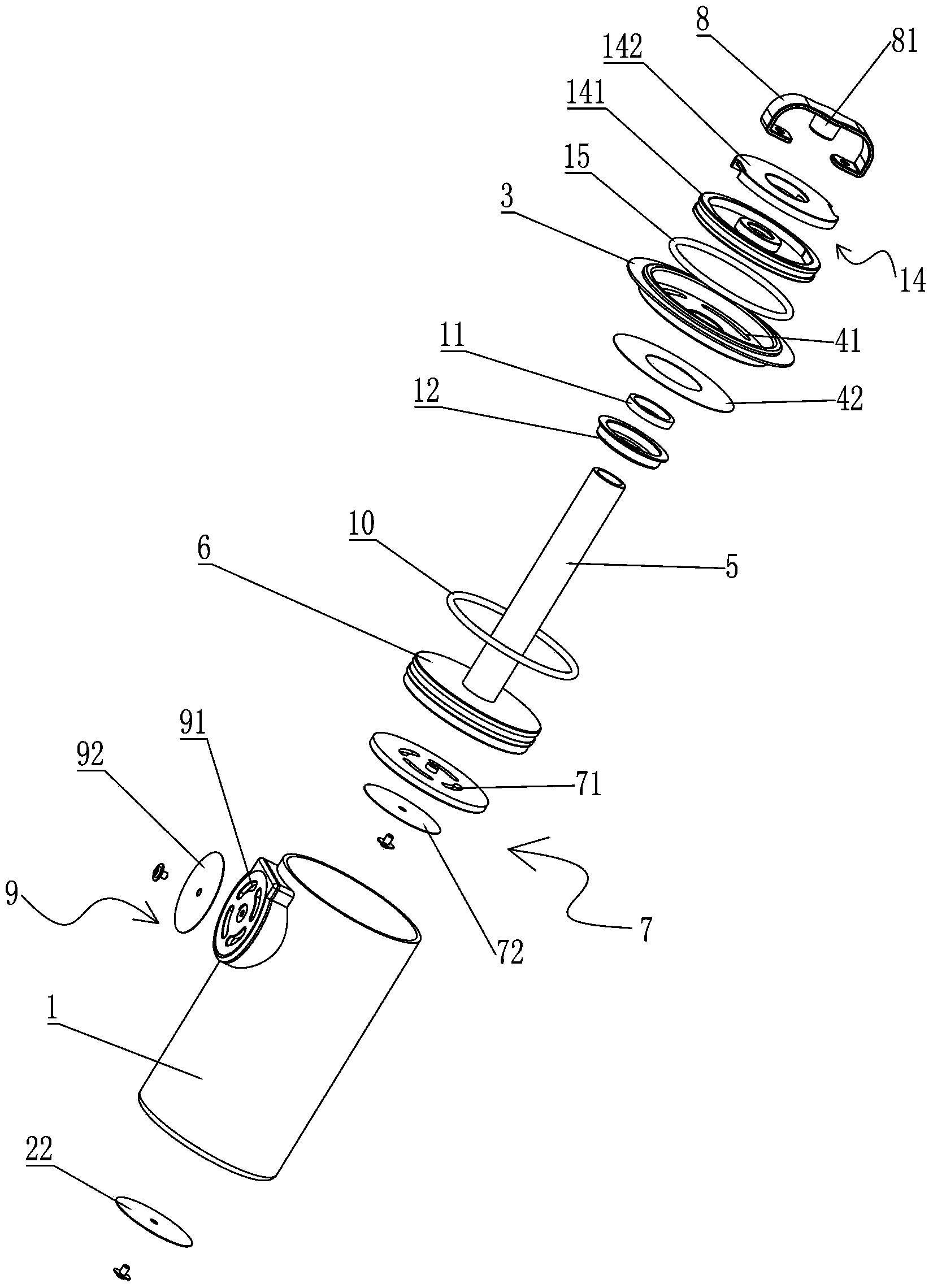
[0031] Such as Figure 1 to Figure 8 As shown, a two-way air pump is characterized in that: it includes a cylinder body 1, a working chamber 101 is provided in the cylinder body 1, and a device communicating with the working chamber 101 is provided at one end of the cylinder body 1 to allow air to flow from The first one-way air outlet valve 2 discharged in the working chamber 101 is provided with a cover 3 at the other end of the cylinder 1, and a cover 3 is provided on the cover 3 to communicate with the working chamber 101 to allow air to be introduced into the valve. The first one-way air intake valve 4 in the working chamber 101 is provided with a push-pull tube 5 in the middle of the cover body 3, and one end of the push-pull tube 5 protruding into the cylinder body 1 is connected with a driving air in the The piston 6 flowing in the working chamber 10...


PUM


Abstract

The invention relates to a two-way inflation pump comprising a barrel. A working chamber is arranged in the barrel, a first one-way air outlet valve communicated with the working chamber to allow air to be discharged from the working chamber is arranged at one end of the barrel, a cover is arranged at the other end of the barrel, a first one-way air inlet valve communicated with the working chamber to allow air to be guided into the working chamber is arranged on the cover, and a push-pull tube is arranged in the middle of the cover penetratingly. One end, extending into the barrel, of the push-pull tube is connected with a piston by which the working chamber is divided into a front working chamber and a rear working chamber. A cavity communicated with the atmosphere through the push-pull tube is formed in the piston. A second one-way air inlet valve, allowing air to be guided into the rear working chamber when the piston is pulled back, is arranged between the cavity and the rear working chamber. The other end of the push-pull tube is combined with a handle. A second one-way air outlet valve, which is communicated with the front working chamber and allows air to be discharged from the front working chamber when the piston is pulled back, is arranged on one side of the wall of the barrel. Inflation can be performed during reciprocation of the piston, and use efficiency is high.

Description

【Technical field】 [0001] The invention relates to a bidirectional air pump. 【Background technique】 [0002] There are quite a few types of air pumps that are operated by the user's hands. The most typical traditional structure is the air pump used by ordinary people to inflate bicycle tires, commonly known as an air pump. This air pump has a cylindrical body. A piston operated by the action rod is assembled in the middle, and a handle is provided on the top of the action rod for the user to hold, and an inflatable tube is extended from the lower end of the body, and a piston is arranged at an appropriate position of the body. When the user pulls up the handle , the air will enter under the piston inside the body, and when the user presses the handle down, the piston will push the air in the body into the inflatable tube, and the inflatable tube will provide an inflation effect. This traditional The air pump of the type is a one-way air pump, that is, it can only provide inf...

Claims


Application Information

Patent Timeline
IPC IPC(8): F04B33/00F04B39/10F04B39/00
Inventor 李树彬龙寿国
Owner JUNHONG PLASTIC PROD CO LTD
Learn More