A pipe pile production feeding system
A feeding system and pipe pile technology, applied in the direction of supply devices, manufacturing tools, etc., can solve the problems of only waiting for the idle stage, the production efficiency of concrete pipe piles cannot be improved, etc., and achieve the effect of improving the utilization rate of equipment
- Summary
- Abstract
- Description
- Claims
- Application Information
AI Technical Summary
Problems solved by technology
Method used
Image

Examples
Embodiment 1
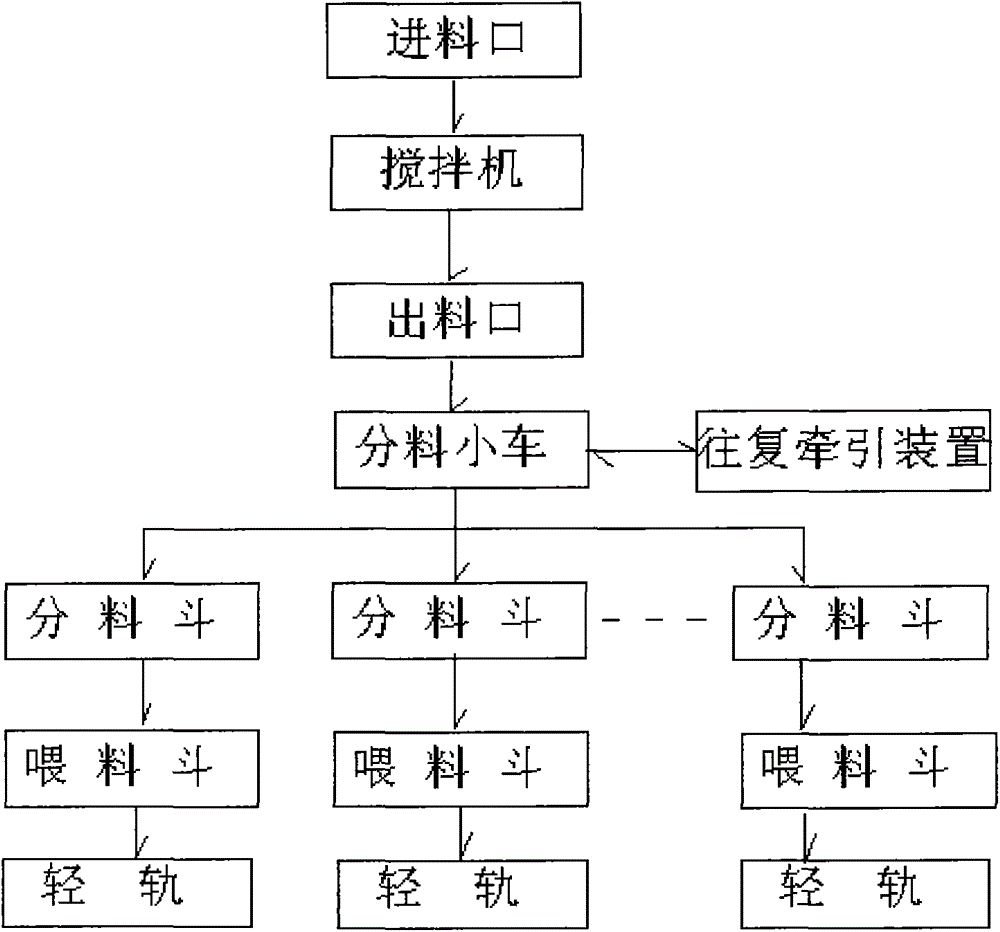
[0014] Example 1, such as figure 1 The feeding system for pipe pile production shown is that the feed inlet of the mixer on the top floor of the mixing building is connected to the conveyor belt, the distribution trolley is located on the second floor below the outlet of the mixer, and the distribution trolley is installed on the guide rail. , and can move back and forth on the guide rail through the reciprocating traction device. The distribution hopper is located on the third floor below the corresponding position of the distribution trolley. There are 3 distribution hoppers, and each distribution hopper is connected to the feeding hopper on the fourth floor. The hopper is fixedly installed on the entire top of the corresponding light rail. There is a flat trolley on the light rail that moves through the light rail traction device. The platform controls the work of each device.
Embodiment 2
[0015] Example 2, such as figure 1 The feeding system for pipe pile production shown is that the feed inlet of the mixer on the top floor of the mixing building is connected to the conveyor belt, the distribution trolley is located on the second floor below the outlet of the mixer, and the distribution trolley is installed on the guide rail. , and can move back and forth on the guide rail through the reciprocating traction device. The distribution hopper is located on the third floor below the corresponding position of the distribution trolley. There are 2 distribution hoppers, and each distribution hopper is connected to the feeding hopper on the fourth floor. The hopper is fixedly installed on the entire top of the corresponding light rail. There is a flat trolley on the light rail that moves through the light rail traction device. The platform controls the work of each device.
Embodiment 3
[0016] Example 3, such as figure 1 The feeding system for pipe pile production shown is that the feed inlet of the mixer on the top floor of the mixing building is connected to the conveyor belt, the distribution trolley is located on the second floor below the outlet of the mixer, and the distribution trolley is installed on the guide rail. , and can move back and forth on the guide rail through the reciprocating traction device. The distribution hopper is located on the third floor below the corresponding position of the distribution trolley. There are 10 distribution hoppers. Each distribution hopper is connected to the feeding hopper on the fourth floor. The hopper is fixedly installed on the entire top of the corresponding light rail. There is a flat trolley on the light rail that moves through the light rail traction device. The platform controls the work of each device.
[0017] This system is applied to the production of concrete pipe piles. According to the productio...
PUM
 Abstract
Description
Claims
Application Information
 - R&D
- Intellectual Property
- Life Sciences
- Materials
- Tech Scout
- Unparalleled Data Quality
- Higher Quality Content
- 60% Fewer Hallucinations
Browse by: Latest US Patents, China's latest patents, Technical Efficacy Thesaurus, Application Domain, Technology Topic, Popular Technical Reports.
© 2025 PatSnap. All rights reserved.Legal|Privacy policy|Modern Slavery Act Transparency Statement|Sitemap|About US| Contact US: help@patsnap.com