
Nanometer positioning device and system

A nano-positioning and macro-positioning technology, which is applied in metal processing and other fields, can solve the problems of difficulty in the development of data acquisition and control modules, the upper limit of the swing angle adjustment amplitude and the limitation of adjustment accuracy, the cost and high cycle time of grating marking machine transformation, and achieve Achieve resolution and positioning accuracy, reduce impact, and reduce development difficulty

Inactive Publication Date: 2014-01-01
CHANGCHUN INST OF OPTICS FINE MECHANICS & PHYSICS CHINESE ACAD OF SCI
View PDF4 Cites 19 Cited by
  • Summary
  • Abstract
  • Description
  • Claims
  • Application Information

AI Technical Summary

Problems solved by technology

[0004] In order to solve the technical problems that the upper limit of the swing angle adjustment amplitude and the adjustment accuracy of the nanopositioning device in the prior art are limited by performance parameters, the difficulty in developing the data acquisition and control module of the nanopositioning system, and the high cost and cycle of the modification of the grating marking machine, this paper The invention provides a nano-positioning device and system

Method used


Image

  • Nanometer positioning device and system
  • Nanometer positioning device and system
  • Nanometer positioning device and system

Examples


Embodiment Construction

[0036] The present invention will be described in further detail below in conjunction with the accompanying drawings.

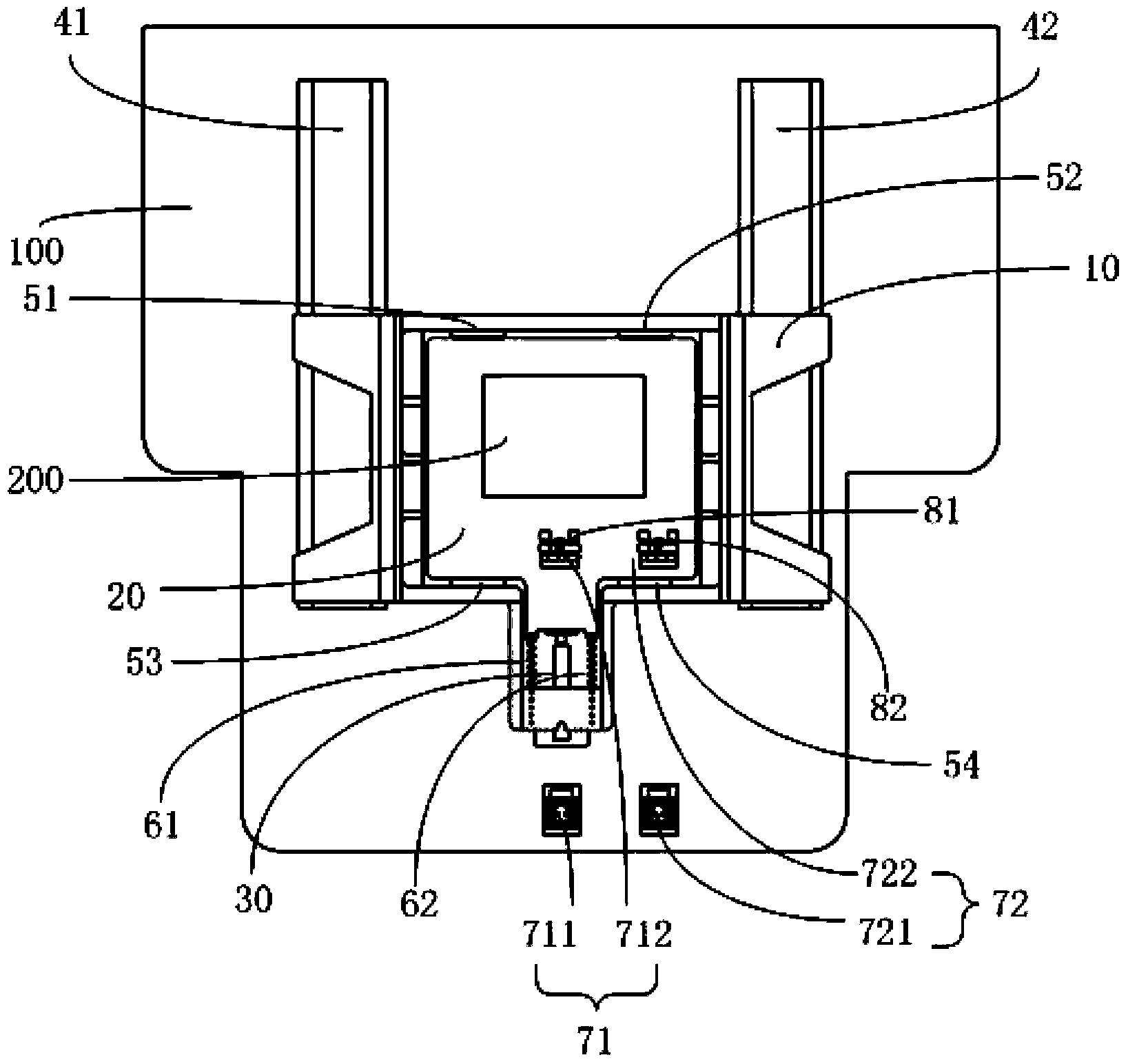
[0037] Such as figure 1 and figure 2 As shown, the nanopositioning device of this embodiment includes a base 100, a macropositioning platform 10, a first guide rail 41, a second guide rail 42, a micropositioning platform 20, piezoelectric ceramics 30, and a first laser interference displacement detection mechanism 71 And the second laser interference displacement detection mechanism 72, wherein, the material of the first guide rail 41 and the second guide rail 42 can be fused silica glass;

[0038] The grating blank 200 is located on the micro-positioning platform 20, and the moving direction of the nano-positioning device is kept perpendicular to the moving direction of the grating cutter;

[0039] The first guide rail 41 and the second guide rail 42 are located at the left and right ends of the lower surface of the macro positioning platform 10 respectiv...


PUM


Abstract

The invention relates to a nanometer positioning device and a nanometer positioning system, belongs to the technical field of automatic control of grating ruling machinery and solves the technical problems that in the prior art, the upper limit of the adjusting amplitude of a tilt angle and the adjusting precision of a nanometer positioning device are limited by the performance parameters, and the data collecting control module of a nanometer positioning system is large in developing difficulty. The nanometer positioning device comprises a substrate, a macro positioning platform, a first guiding guide track, a second guiding guide track, a micro-positioning platform, piezoelectric ceramic, a first laser interference displacement detection mechanism and a second laser interference displacement detection mechanism; one end of the piezoelectric ceramic is fixed on the macro positioning platform while the other end is contacted with the micro-positioning platform; the macro positioning platform slides along the first and second guiding guide tracks; the piezoelectric ceramic drives the micro-positioning platform to generate displacement. The invention also provides the nanometer positioning system applying the nanometer positioning device. The nanometer positioning device and the nanometer positioning system have a larger upper limit of the adjusting amplitude of the tilt angle and adjusting flexibility.

Description

technical field [0001] The invention relates to a nanometer positioning device and system, belonging to the field of automatic control of grating marking machinery. Background technique [0002] Nanopositioning technology is widely used in various fields such as superfinishing, microelectronics engineering, bioengineering, and nanotechnology. When the nanopositioning system is used in the grating mechanical scribing process, the movement direction of the nanopositioning system is kept perpendicular to the movement direction of the grating cutter. Due to the swing angle error of the nanopositioning system, the grating lines are not parallel, that is, there is a swing angle error of the grating line, which directly leads to the degradation of the grating quality and the increase of the stray light of the grating. [0003] Nanopositioning devices in the prior art generally use two or more piezoelectric ceramics to double-layer worktables (the double-layer workbench includes a ...

Claims


Application Information

Patent Timeline
Patent Type & Authority Applications(China)
IPC IPC(8): B26D7/00B26D5/00B26D3/08
Inventor 于海利李晓天唐玉国齐向东于宏柱杨超
Owner CHANGCHUN INST OF OPTICS FINE MECHANICS & PHYSICS CHINESE ACAD OF SCI
Learn More