Crushing machine

A pulverizer and crushing layer technology, which is applied in the field of mechanical equipment, can solve problems such as waste of operation time, slow operation speed, and complex structure, and achieve the effects of increasing service life, improving crushing rate, and being convenient to use

Inactive Publication Date: 2014-01-01
常熟市新晨机械厂
View PDF8 Cites 4 Cited by
  • Summary
  • Abstract
  • Description
  • Claims
  • Application Information

AI Technical Summary

Problems solved by technology

[0002] With the development of social production and the rapid development of the machinery industry, a large number of pulverizers are produced and used. With the extensive development of the construction industry, the role of pulverizers in operations cannot be ignored. The application number is CN 201210417917.2, which discloses a The pulverizer includes a chassis, a base, a motor, and a main shaft. The chassis and the motor are fixedly arranged on the base. The main shaft runs through the chassis. A roller and a fixed knife are arranged inside the chassis. The roller includes an end cover , hanging rod, hammer, the number of the end caps is two, the two end caps are fixed on the main shaft, a hanging rod is also arranged between the two end caps, and the two ends of the hanging rods are fixed Connected to the end cover, several hammers are installed on the hanging rod, and one end of the hammer is connected to the hanging rod in rotation; the fixed knife is fixed on the fixed knife shaft in the chassis, and the fixed knife It is arranged directly below the drum, and the fixed knife is interlaced with the hammer at the bottom of the drum. One side of the cabinet is provided with an air inlet, and the air inlet is connected to the cabinet. The invention provides a crushing Small particles, low power consumption, simple structure and high efficiency pulverizer, but the cutting speed of the pulverizer blade is small, the ability to pulverize objects is weak, the operation speed is slow, the operation time is wasted, the operation efficiency is low, and the structure is complicated

Method used


Image

  • Crushing machine

Examples


Embodiment Construction

[0011] In order to make the technical means, creative features, goals and effects achieved by the present invention easy to understand, the present invention will be further described below in conjunction with specific embodiments.

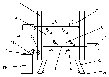
[0012] Such as figure 1 As shown, a pulverizer includes a housing 1 and a pulverizing device 2, a frame 2 is provided below the housing 1, and the pulverizing device 2 includes a first pulverizing layer 7 and a second pulverizing layer 8, and the first pulverizing layer 8 A pulverizing layer 7 and the second pulverizing layer 8 all comprise motor 4, rotating shaft 5 and blade 6, and described blade 6 is arranged on rotating shaft 5, and described blade 6 is S shape, and during work, the first pulverizing layer and the 2nd pulverizing layer The rotating shafts of the two crushing layers have different turning directions, which have double crushing effects, evenly stirred, can crush the materials more fully, improve the crushing rate, and have a si...


PUM


Abstract

The invention discloses a crushing machine, which relates to the field of machinery equipment. The crushing machine comprises a shell and a crushing device, wherein a rack is arranged below the shell; the crushing device comprises a first crushing layer and a second crushing layer; each of the first crushing layer and the second crushing layer comprises a motor, a rotating shaft and blades; the S-shaped blades are arranged on the rotating shafts. When the crushing machine works, the rotating shafts of the first and the second crushing layer rotate in different directions, thus achieving a double crushing effect and stirring uniformly. The crushing machine can fully crush materials and improve a crushing rate, and is simple in structure and convenient to use.

Description

technical field [0001] The invention relates to the field of mechanical equipment, in particular to a pulverizer. Background technique [0002] With the development of social production and the rapid development of the machinery industry, a large number of pulverizers are produced and used. With the extensive development of the construction industry, the role of pulverizers in operations cannot be ignored. The application number is CN 201210417917.2, which discloses a The pulverizer includes a chassis, a base, a motor, and a main shaft. The chassis and the motor are fixedly arranged on the base. The main shaft runs through the chassis. A roller and a fixed knife are arranged inside the chassis. The roller includes an end cover , hanging rod, hammer, the number of the end caps is two, the two end caps are fixed on the main shaft, a hanging rod is also arranged between the two end caps, and the two ends of the hanging rods are fixed Connected to the end cover, several hammers...

Claims


Application Information

Patent Timeline
Patent Type & Authority Applications(China)
IPC IPC(8): B02C18/14B02C18/16
Inventor 张德生
Owner 常熟市新晨机械厂
Why Eureka
Try Eureka