
Method of splicing laminated floor slab and beam

A technology of superimposing floor slabs and slab thicknesses, which is applied in the processing of building materials, construction, building construction, etc., can solve the problems of unsatisfactory structural requirements and unreasonable force at joints, and achieve reasonable force and simple construction Effect

Inactive Publication Date: 2013-12-25
NANJING UNIV OF TECH
View PDF5 Cites 13 Cited by
  • Summary
  • Abstract
  • Description
  • Claims
  • Application Information

AI Technical Summary

Problems solved by technology

This approach cannot meet the structural requirements in the national code, and the force at the nodes is unreasonable

Method used


Image

  • Method of splicing laminated floor slab and beam
  • Method of splicing laminated floor slab and beam

Examples


Embodiment Construction

[0012] The present invention will be further described below in conjunction with the accompanying drawings and specific embodiments.

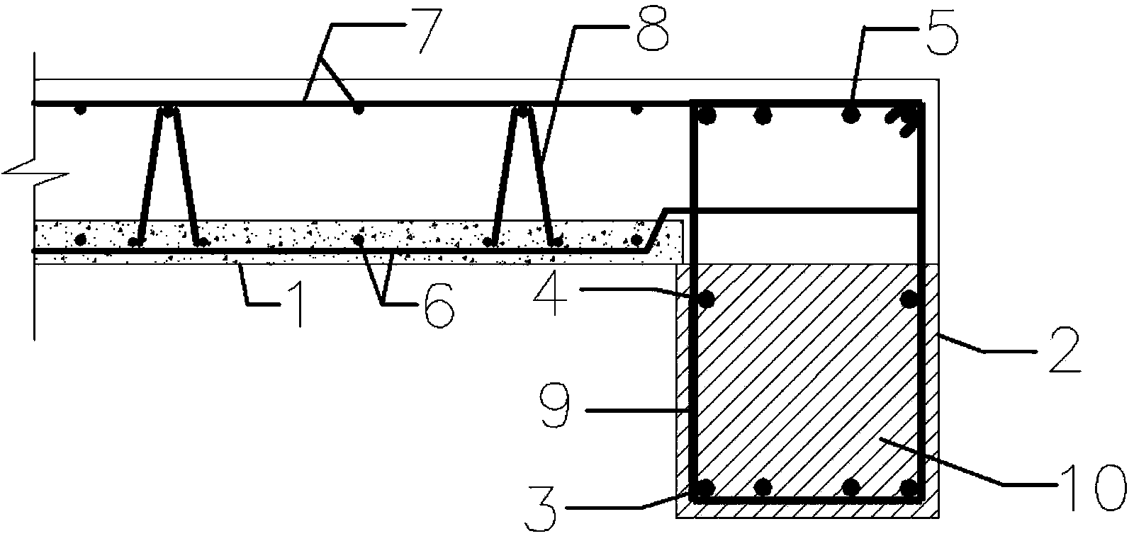
[0013] like figure 1 and figure 2 As shown, the prefabricated slab is prefabricated in the factory and is composed of slab bottom steel bar 6, truss steel bar 8 and concrete, among which the truss steel bar 8 can control the thickness of the floor slab. The prefabricated panels can act as templates on site, eliminating the need for formwork.

[0014] During on-site construction, first bind the steel bars inside the beam 2, and pay attention to only binding the longitudinal bars 3 at the lower part of the beam, the longitudinal bars 4 at the middle of the beam and the stirrup bars 9 during the first pouring. The height of the formwork should not be higher than the difference between the beam height and the plate thickness when the beam formwork is supported. After the formwork is completed, the concrete is poured, and the first pouring part 1...


PUM


Abstract

The invention discloses a method of splicing a laminated floor slab and a beam. The method comprises the following steps of providing a precast slab, a beam, a lower longitudinal bar of the beam, a middle longitudinal bar of the beam, an upper longitudinal bar of the beam, a reinforcing steel bar at the slab bottom, an additional reinforcing steel bar at the slab top, a truss bar and a hooping; pouring the beam at two times, wherein the first pouring height is a difference between the beam depth and the thickness of the slab, and only binding the lower longitudinal bar of the beam, the middle longitudinal bar of the beam and the hooping in the beam during the pouring; when cast-in-place concrete reaches a certain intensity, hoisting the precast slab, placing slab edges at the side of the beam, and extending the reinforcing steel bar at the slab bottom into the beam; lastly, adding the upper longitudinal bar of the beam and the additional reinforcing steel bar at the slab top, and casting the concrete in place again so as to complete construction of the beam and the slab. According to the method described by the invention, the reinforcing steel bar at the edge of the slab can be accurately anchored in the beam so as to meet requirements of current specifications of nation, and the method has the advantages of simple construction and reasonable stress.

Description

technical field [0001] The invention relates to a method for splicing prefabricated assembled concrete laminated floors and beams, and belongs to the construction field of prefabricated assembled structures in construction engineering. Background technique [0002] In order to promote the development of construction industrialization, the state has vigorously advocated prefabricated buildings in recent years. As an important structural component in the structural system, the laminated floor slab has a high degree of industrialization. The laminated slab is composed of prefabricated parts and cast-in-place parts. It has the characteristics of high industrialization of prefabricated assembly and good integrity of cast-in-place structures. Among them, the prefabricated part is produced in the factory and has a fixed production mode. During on-site construction, the prefabricated panel is not only a part of the structure, but also acts as a formwork, eliminating the need for f...

Claims


Application Information

Patent Timeline
IPC IPC(8): E04G21/00
Inventor 叶燕华张诗浩孙锐薛洲海宋妍陈浩李炎
Owner NANJING UNIV OF TECH
Learn More