
Integrated pipe trench structure applied to interregional ground line roadbed of urban rail transit project

A technology for integrated pipe trenches and traffic engineering, applied in water conservancy projects, underwater structures, infrastructure engineering, etc., can solve the problems of unfavorable inspection equipment handling, increase the width of the project land occupation, aging of pipeline equipment, etc., and achieve easy walking and equipment handling, saving project area, and avoiding the effect of wind and sun

Active Publication Date: 2013-12-25
CHINA RAILWAY DESIGN GRP CO LTD
View PDF7 Cites 4 Cited by
  • Summary
  • Abstract
  • Description
  • Claims
  • Application Information

AI Technical Summary

Problems solved by technology

[0003] At present, different urban rail projects in different regions have different pipeline layout forms. In some projects, the comprehensive pipeline is arranged in the form of brackets, and the cables are exposed above the ground. The pipeline equipment is easy to age due to wind and sun. On both sides, it is not safe, it is not conducive to inspection and equipment handling, and it also increases the width of the project.
Some project pipelines adopt pipe trench type radiation, but without reasonable synthesis, the arrangement is not concentrated, the structure is not compact, the land occupation is large, and the type is not perfect

Method used


Image

  • Integrated pipe trench structure applied to interregional ground line roadbed of urban rail transit project
  • Integrated pipe trench structure applied to interregional ground line roadbed of urban rail transit project
  • Integrated pipe trench structure applied to interregional ground line roadbed of urban rail transit project

Examples


Embodiment Construction

[0014] The comprehensive pipe trench structure applied to the subgrade of the ground line in the urban rail transit engineering section of the present invention will be described in conjunction with the accompanying drawings and embodiments.

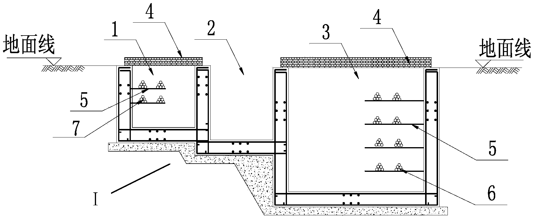
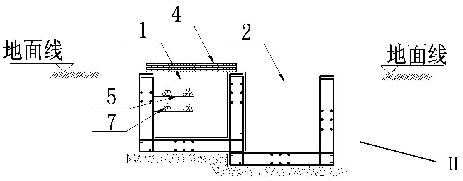
[0015] like figure 1 , 2 , shown in 3, the comprehensive pipe ditch structure of the present invention that is applied to the subgrade of the ground line in the urban rail transit project interval is that the comprehensive pipe ditch includes a strong electric pipe ditch 3, a weak electric pipe ditch 1, and a drainage pipe ditch 2, and is distributed in On both sides of the roadbed of the urban rail ground line, the comprehensive pipe trenches on both sides are laid parallel to the roadbed of the line, and the cross-sectional structure of the comprehensive pipe trench I on the one side includes a weak current pipe ditch 1, a drainage ditch 2, and a strong electric pipe ditch 3, The cross-sectional structure of the comprehensive pipe dit...


PUM


Abstract

The invention provides an integrated pipe trench structure applied to an interregional ground line roadbed of an urban rail transit project. The integrated pipe trench structure comprises a heavy-current pipe trench, weak-current pipe trenches and drainage trenches and is distributed at the two sides of a ground line roadbed of the urban rail transit project, wherein integrated pipe trenches at the two sides are laid parallel to the line roadbed, the cross-sectional structure of the integrated pipe trench I at one side comprises one weak-current pipe trench, one drainage trench and the heavy-current pipe trench, the cross-sectional structure of the integrated pipe trench II at the other side comprises one weak-current pipe trench and one drainage trench, and cover plates are respectively arranged at the tops of the heavy-current pipe trenches and the tops of the weak-current pipe trenches. The integrated pipe trench structure has the effects that the layout is compact, the arrangement is reasonable, the mutual interference is avoided, the width of the roadbed is reduced, and the floor occupation of the project is reduced; the movable cover plates are arranged, the opening is facilitated so as to inspect and repair cables, and the cables can be excellently protected from wind and sun; the pipe trenches are provided with longitudinal slopes with the gradient not lower than 0.02%, so that water accumulated in the trenches can be removed in time.

Description

technical field [0001] The invention relates to a comprehensive pipe ditch structure applied to the subgrade of ground lines in urban rail transit engineering sections. Background technique [0002] In urban rail transit projects, the comprehensive pipeline system is an important part of engineering equipment. It is composed of cables for power supply systems, cables or optical cables for communication systems, cables for signal systems, and grooved pipelines for water supply and drainage systems. Their reasonable The layout is to ensure the normal function of each pipeline system, avoid mutual interference, and make the layout as compact as possible to reduce the occupation of more space. In urban rail transit projects, the layout types are different under different line laying methods. [0003] At present, different urban rail projects in different regions have different pipeline layout forms. In some projects, the comprehensive pipeline is arranged in the form of bracket...

Claims


Application Information

Patent Timeline
Patent Type & Authority Applications(China)
IPC IPC(8): E02D29/045
Inventor 马振海张永利郭伟孙继忠耿广晋那艳玲刘乃宗王立存
Owner CHINA RAILWAY DESIGN GRP CO LTD
Learn More