Pipe pressing device for galvanizing machine

A technology of pressing pipes and pressing plates, which is applied in hot-dip galvanizing process, metal material coating process, coating, etc. It can solve the problems of steel pipe bending, jamming, steel pipe floating, etc., and achieves long service life and easy disassembly and replacement of parts. Convenience, easy installation effect

Active Publication Date: 2013-12-25
ZHEJIANG KINGLAND PIPELINE & TECH CO LTD
View PDF5 Cites 0 Cited by
  • Summary
  • Abstract
  • Description
  • Claims
  • Application Information

AI Technical Summary

Problems solved by technology

[0002] In the steel pipe galvanizing process, the front end of the galvanized steel pipe will be placed on the conveyor device that extends into the galvanizing pool obliquely, and will be sent out of the galvanizing pool by the conveyor device. Most types of steel pipes can be sent out of the galvanizing pool smoothly. When the steel pipe with large inner diameter is galvanized, the zinc liquid easily enters the steel pipe. After galvanizing, there will not be a lot of air in the steel pipe, and the steel pipe will sink with its own gravity. The steel pipe with a smaller inner diameter has a smaller lumen. Although the zinc liquid is not easy to pour into the lumen, due to the small diameter of the pipe, even if there is air in the lumen after galvanizing, it is not enough to float the steel pipe
In the actual galvanizing process, after galvanizing a steel pipe with an outer diameter of 20-22mm and a wall thickness of 1.6mm or less, there will be a large amount of air in the steel pipe, which is enough to offset the weight of the steel pipe and suspend the steel pipe in the pool. The rear end is tilted, so that when the conveyor is transported along the inclined conveyor, the front end of the steel pipe will be against some parts of the conveyor, causing the steel pipe to bend or get stuck during the conveying process

Method used


Image

  • Pipe pressing device for galvanizing machine
  • Pipe pressing device for galvanizing machine
  • Pipe pressing device for galvanizing machine

Examples


Embodiment 1

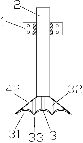
[0034] A pipe pressing device for a galvanizing machine, comprising a guide sliding sleeve 1, a pressing rod 2 provided on the guiding sliding sleeve 1 and capable of moving up and down along the guiding sliding sleeve 1, a pressing plate part arranged at the bottom end of the pressing rod 2 and connecting The power part at the top of the pressure rod 2. The pressure plate component includes a pressure plate seat connected to the bottom end of the pressure rod 2 and a pressure plate 3 arranged at the bottom of the pressure plate seat. The pressure plate 3 is concavely formed with several pressure plate grooves 31 with arc-shaped cross-sections and arranged in parallel. The arc-shaped transition section passes between the pressure plate grooves 31 33 connections.

[0035] The pressure plate seat includes two inclined and symmetrically arranged side plates 42 , the angle between the side plates 42 is 100 degrees, and the bottom ends of the two side plates 42 are respectively con...

Embodiment 2

[0038] The difference from the above embodiment is that the pressing plate part and the pressing bar are detachably connected, and there are three pressing plate grooves 31 . The notch span of the pressing plate groove 31 is 25mm, and the groove depth is 10mm. The angle between the side plates 42 is 120 degrees

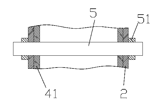
[0039] A connecting rod 41 for connecting the pressing rod 2 is arranged on the top of the pressing plate seat, and the connecting rod 41 is detachably sleeved on the pressing rod 2 . The connecting rod 41 is connected with the pressing rod 2 through the insertion rod 5 passing through the connecting rod 41 and the pressing rod 2 transversely, and the two ends of the insertion rod 5 are provided with fixing parts 51 . There are external threads at both ends of the insertion rod, and the fixing part is a nut matched with the external threads. The connecting rod 41 or the pressing rod 2 is provided with an in-line adjustment hole 6 for passing through the insertion ro...

Embodiment 3

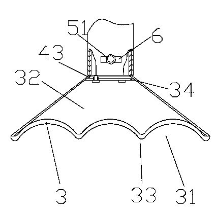
[0041] The difference from the above embodiment is that the top of the side plate 42 is connected by the top plate 43 , the reinforced support member 32 is a reinforced support plate, and the top of the reinforced support plate is provided with a connecting plate 34 detachably connected to the top plate 43 . The connecting plate is detachably connected with the top plate through bolts. The pressure plate is easy to replace and disassemble. The pressing plate 3 is provided with six pressing plate grooves 31, the span of the openings of the pressing plate grooves 31 is 30 mm, and the groove depth is 15 mm. The angle between the side plates 42 is 130 degrees

[0042] A pipe pressing device is installed on the galvanizing pool, so that the rear end of the steel pipe with an outer diameter of 20-22 mm and a wall thickness of 1.6 mm or less is smoothly pressed down after galvanizing, and there is still a large amount of air in the lumen. The inclination angle of the steel pipe is ...


PUM


Abstract

The invention belongs to the field of galvanizing and processing of steel pipes and specifically relates to a pipe pressing device for a galvanizing machine. The pipe pressing device comprises a guide sliding sleeve, a pressing rod, a pressing plate part and a power part, wherein the pressing rod is arranged on the guide sliding sleeve and is capable of moving up and down along the guide sliding sleeve; the pressing plate part is arranged on the bottom end of the pressing rod; the power part is connected with the top end of the pressing rod; the pressing plate part comprises a pressing plate base connected with the bottom end of the pressing rod and a pressing plate arranged on the bottom of the pressing plate base; a plurality of pressing plate grooves with arc sections in parallel arrangement are concavely formed in the pressing plate; the pressing plate grooves are connected through an arc transition section; a galvanizing pond is provided with a pipe pressing device; after galvanizing, a large amount of air still exists in a pipe cavity of a steel pipe with an external diameter of 20-22mm and a wall thickness less than or equal to 1.6mm, so that the rear end of the steel pipe is smoothly pressed downwards; the inclination angle of the pressed steel pipe is similar to that of a transmission device, so that the steel pipe is smoothly transmitted out of the galvanizing pond; the faults that the steel pipe is bent or the device is jammed and the like cannot occur in the transmission process, so that the working efficiency is improved.

Description

technical field [0001] The invention belongs to the field of galvanizing processing of steel pipes, and in particular relates to a pipe crimping device for a galvanizing machine. Background technique [0002] In the steel pipe galvanizing process, the front end of the galvanized steel pipe will be placed on the conveyor device that extends into the galvanizing pool obliquely, and will be sent out of the galvanizing pool by the conveyor device. Most types of steel pipes can be sent out of the galvanizing pool smoothly. When the steel pipe with large inner diameter is galvanized, the zinc liquid easily enters the steel pipe. After galvanizing, there will not be a lot of air in the steel pipe, and the steel pipe will sink with its own gravity. The steel pipe with a smaller inner diameter has a smaller lumen. Although the zinc liquid is not easy to pour into the lumen, even if there is air in the lumen after galvanizing due to the small diameter of the pipe, it is not enough to ...

Claims


Application Information

Patent Timeline
IPC IPC(8): C23C2/38
Inventor 沈百方李善福熊俊波费建芳陈连堂沈百荣史志伟
Owner ZHEJIANG KINGLAND PIPELINE & TECH CO LTD
Why Eureka
Try Eureka