
Automatic locking screw device

An automatic locking screw and screw technology, which is applied in metal processing equipment, metal processing, manufacturing tools, etc., can solve the problems of high difficulty of locking, inability to clamp and arrange, and affect the correctness of assembly tightness and assembly, so as to reduce the Labor cost, the effect of mass production labor cost

Inactive Publication Date: 2015-12-16
TERA AUTOTECH CORP
View PDF7 Cites 0 Cited by
  • Summary
  • Abstract
  • Description
  • Claims
  • Application Information

AI Technical Summary

Problems solved by technology

But in contrast, the size and function of the digital products used, such as computers, communication electronics and consumer electronics (ConsumerElectronic), are constantly evolving. It has reached a situation of less than 2 mm, so the screw delivery and arrangement method disclosed in the aforementioned U.S. Patent Publication No. 20120067176 cannot be clamped and arranged for use when the screw is less than 2 mm, let alone a screw locking machine work on locking
The size of the screw is getting smaller and smaller, and the difficulty of locking is getting higher and higher. In addition to the above-mentioned situations, there are often situations where the screw hole and the screw cannot be locked in place precisely.
In addition, under the precision requirements of various electronic products at present, if the screw is not fully locked into the screw hole, its protruding height will often affect the tightness and correctness of subsequent assembly. There is indeed room for improvement. necessary

Method used


Image

  • Automatic locking screw device
  • Automatic locking screw device
  • Automatic locking screw device

Examples


Embodiment Construction

[0023] Relevant detailed description and technical contents of the present invention are as follows with regard to coordinating illustrations now:

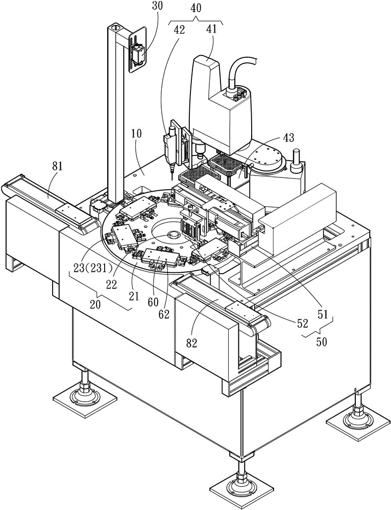
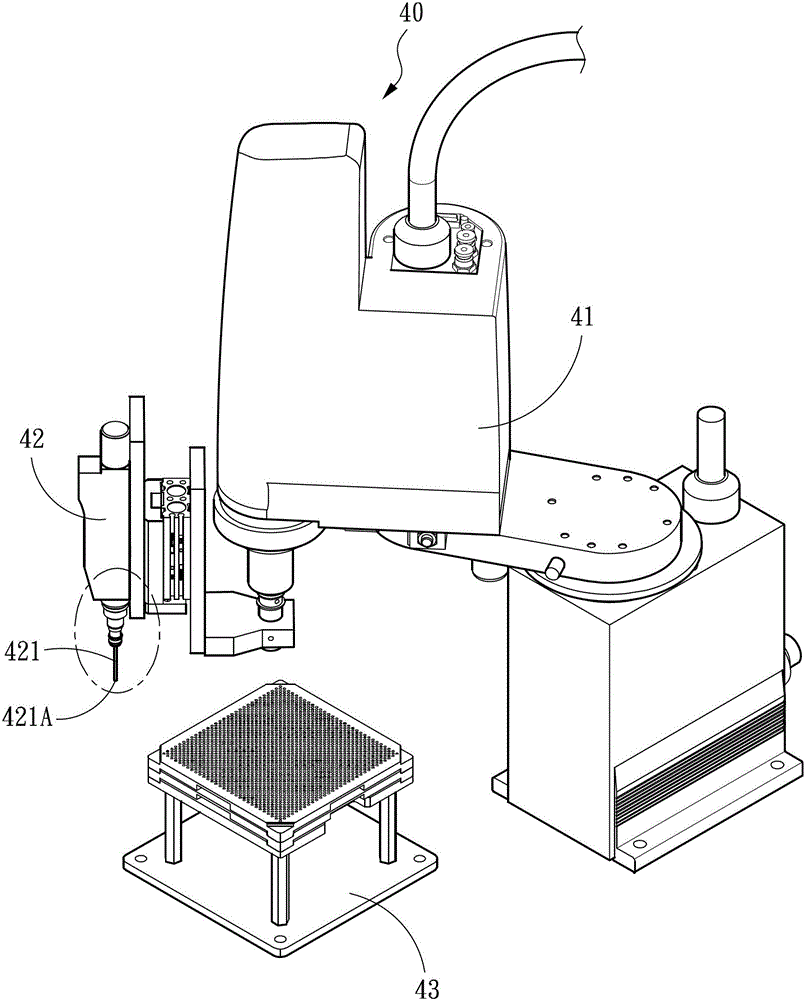
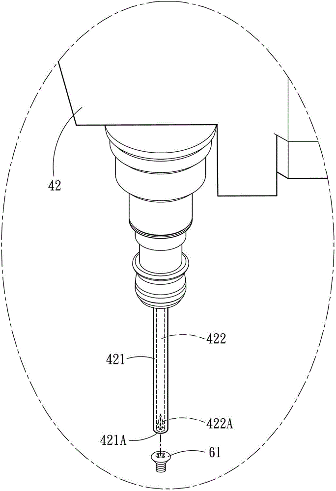
[0024] see figure 1 and Figure 4A to Figure 4C As shown, the present invention is an automatic locking screw device, which is used to lock at least one screw 61 (shown in Figure 2B ) into a screw hole 62 on a working object 60, the automatic screw locking device includes a working platform 10, a carrying mobile platform 20, an image observation module 30 for observing the position of the screw hole on the working object 60, together with A screw placement part 43 obtains the at least one screw 61 and locks it into the screw locking module 40 of the working object 60 , and a locking detection module 50 checks whether the screw 61 is locked correctly.

[0025] The carrying mobile platform 20 has a carrying part 21 for carrying and fixing the working object 60, and a moving part 22 connected with the carrying part 21. In this emb...


PUM


Abstract

An automatic screw locking device is used for locking at least one screw into a screw hole in a workpiece; the automatic screw locking device comprises a worktable, a loading moving table, an image observation module, a screw locking module and a locking detection module; the loading moving table is provided with a loading part for loading and fixing the workpiece, and a moving part; the moving part is used for controlling the workpiece to sequentially reach a first position, a second position and a third position to respectively correspond to the image observation module, the screw locking module and the locking detection module, so position determining of the screw hole, locking of the screw and the examining on the right locking of the screw can be respectively carried out. By the automatic screw locking device, the combining speed can be effectively accelerated and the locking correctness can be effectively improved, and the aims of mass production and reduction of production cost can be achieved.

Description

technical field [0001] The invention relates to a mechanical automation device, in particular to an automatic screw locking device. Background technique [0002] Automated machinery replaces the consumption of human labor and speeds up production and reduces costs. In the combination of parts, most of them need to use screws to fix the combination of multiple objects. In order to increase production efficiency and reduce costs, it is a quick solution to use automatic equipment for screw locking, such as US Patent Publication No. 20120067176 No. AUTOMATIC SCREW TIGHTENING APPARATUS, and China Taiwan Patent Publication No. M399770 automatic locking screw machine, which respectively disclose the way and mechanism of automatic screw locking. [0003] With the continuous advancement of integrated circuit technology and design, the performance and functions of electronic components of the same size are far beyond the previous design. But in contrast, the size and function of the...

Claims


Application Information

Patent Timeline
Patent Type & Authority Patents(China)
IPC IPC(8): B23P19/06
Inventor 李义隆
Owner TERA AUTOTECH CORP
Learn More