Eureka AIR delivers breakthrough ideas for toughest innovation challenges, trusted by R&D personnel around the world.

Manual puncher

A manual punching and punching machine technology, applied in the field of punching machines, can solve the problems of high automatic production cost, high production cost, and inability to start automatic production, and achieve the effects of convenient implementation, low cost, and simple structure

Active Publication Date: 2013-12-25
ZHANGJIAGANG XIAFEI PLASTIC
View PDF6 Cites 8 Cited by
  • Summary
  • Abstract
  • Description
  • Claims
  • Application Information

AI Technical Summary

Problems solved by technology

[0003] However, in some specific fields, it cannot carry out automated production, or the cost of automated production is very high. For small enterprises, they can only choose manual. If automated equipment is used, the production cost is very high

Method used


Image

  • Manual puncher
  • Manual puncher

Examples


Embodiment Construction

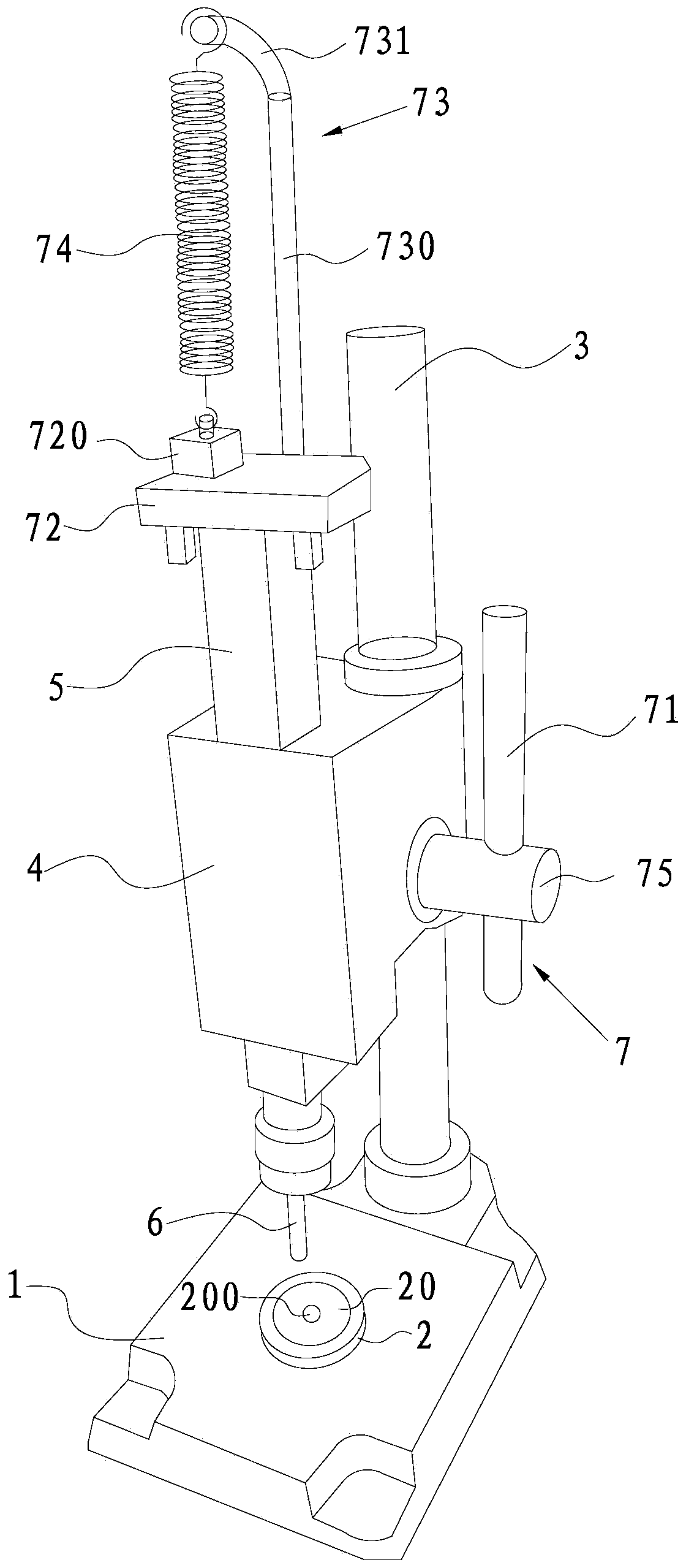
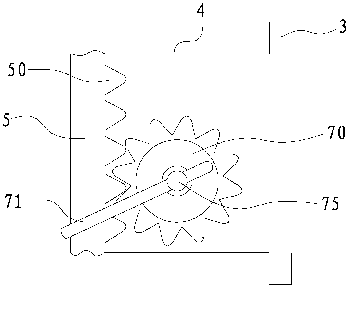
[0017] Such as figure 1 and figure 2 As shown, the manual punching machine provided in this embodiment includes a bottom mold 2 arranged on the work surface 1, a positioning column 3 vertically arranged on the work surface 1, sleeved on the positioning column 3 and positioned on the bottom mold 2 The upper positioning module 4, the mandrel 5 parallel to the positioning column 3 and arranged on the positioning module 4, the hole needle 6 arranged at the lower end of the mandrel 5, and the adjustment mandrel 5 moving up and down along its own length direction The adjustment mechanism 7.

[0018] In this example, the above-mentioned bottom mold 2 has a positioning groove 20 for placing parts to be processed, the hole needle 6 is located directly above the positioning groove 20 , and a hole 200 matching the hole needle 6 is provided at the bottom of the positioning groove 20 .

[0019] At the same time, a rack 50 is provided on the side of the mandrel 5 relative to the position...


PUM


Abstract

The invention discloses a manual puncher. The manual puncher comprises a bottom mold arranged on a working table surface, a positioning column vertically arranged on the working table surface, a positioning module which is sleeved on the positioning column above the bottom mold, a core shaft which is parallel to the positioning column and arranged on the positioning module, a punching needle arranged at the lower end of the core shaft and an adjusting mechanism which is used for adjusting the core shaft to move vertically in the self length direction. The bottom mold is provided with a positioning slot for placing a part to be processed, the punching needle is disposed right above the positioning slot, the bottom of the positioning slot is provided with a hole matched with the punching needle. According to the manual puncher, the adjusting mechanism controls the core shaft to move vertically in the self length direction, so that the punching needle can penetrate the hole of the positioning slot of the bottom mold to achieve workpiece punching. The manual puncher is simple in structure, easy to operate and low in cost.

Description

technical field [0001] The invention relates to a punching machine, in particular to a manual punching machine. Background technique [0002] Drilling machine, a very common equipment in a machinery factory, can also be called a drilling machine, but there is still a difference between punching and drilling. For drilling, a driving mechanism is needed to drive the rotation of the drill bit; for drilling, the other The drill bit does not necessarily need a driving mechanism. For example, a desktop manual punching machine mainly uses a hole needle to match the hole provided on the bottom mold to complete the punching of the bound document. [0003] However, in some specific fields, it cannot carry out automated production, or the cost of automated production is very high. For small enterprises, they can only choose the manual method. If automated equipment is used, the production cost is very high. Contents of the invention [0004] The technical problem to be solved by the...

Claims


Application Information

Patent Timeline
Patent Type & Authority Applications(China)
IPC IPC(8): B21D28/24
Inventor 徐岳年
Owner ZHANGJIAGANG XIAFEI PLASTIC
Why Eureka
Eureka Blog
Learn More