
Bladeless fan structure

A bladeless fan and fan assembly technology, which is applied to liquid variable volume machinery, non-variable volume pumps, variable volume pump components, etc. Effects of flow and noise, low noise, low wind loss

Active Publication Date: 2013-12-18
FOSHAN AARON APPLIANCE CO LTD
View PDF8 Cites 4 Cited by
  • Summary
  • Abstract
  • Description
  • Claims
  • Application Information

AI Technical Summary

Problems solved by technology

[0003] The invention provides a structure with simple structure, good air outlet effect, hard deformation of the shell, and can be combined with the fan assembly to form a structure of a bladeless fan with low running noise; it solves the shell of the bladeless fan existing in the prior art The air outlet needs to be equipped with a spacer, the processing requirements are high, there are many components, and the technical problem of resonance is easy to occur

Method used


Image

  • Bladeless fan structure
  • Bladeless fan structure
  • Bladeless fan structure

Examples


Embodiment 1

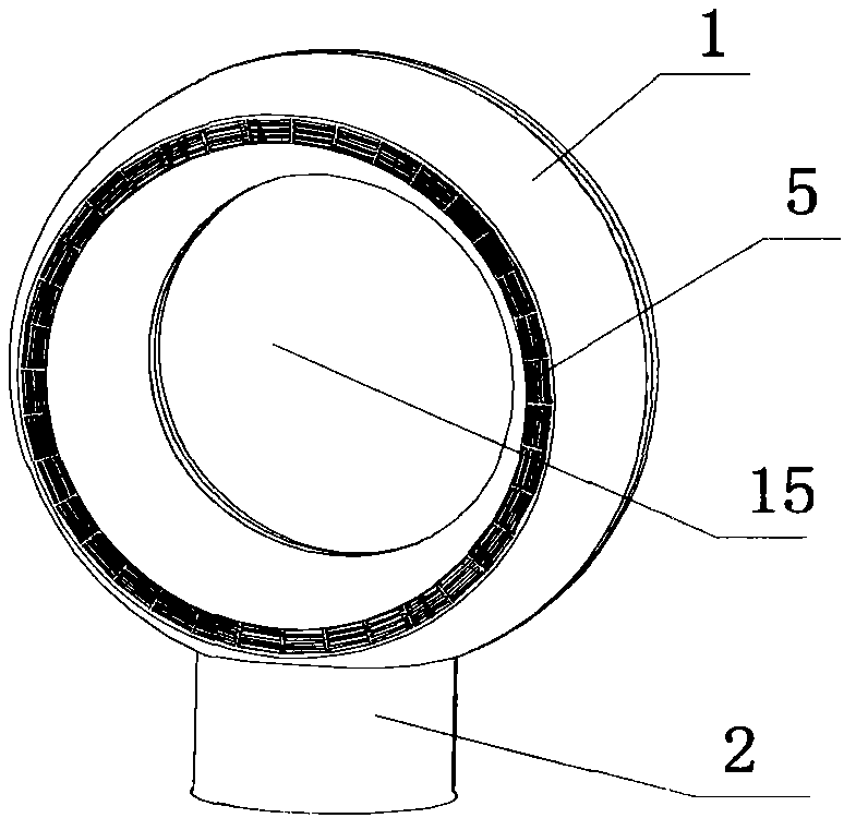
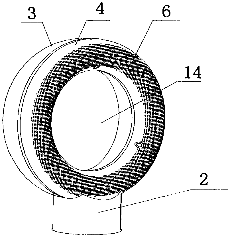
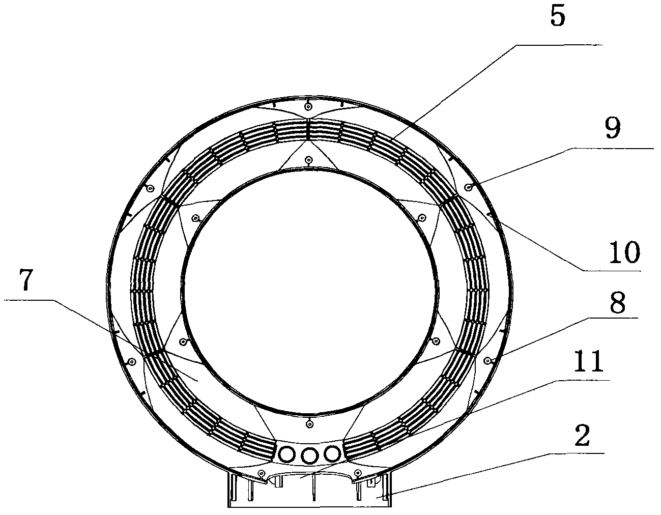
[0021] like figure 1 and 2 As shown, a bladeless fan structure includes a circular housing 1, a cylindrical connection body 2 is connected below the housing 1, and the axis of the housing 1 and the axis of the connection body 2 are perpendicular to each other. The case 1 is composed of a front case 3 and a rear case 4 . Both the front casing 3 and the rear casing 4 are circular. The cross-sections of the front housing 3 and the rear housing 4 are "U"-shaped, and the width of the cross-section of the front housing is narrowed from the opening end of the "U" shape to the connecting end of the "U" shape. The width of the cross section is the same. An air outlet 5 is provided on the front housing 3 . The air outlet 5 is annular. The rear housing 4 is provided with an air inlet 6, the air inlet 6 is annular, the air inlet 6 and the air outlet 5 are parallel to each other, and the air inlet 6 is formed by uniformly distributed circular holes arranged on the rear housing. The wi...

Embodiment 2

[0025] like Figure 7 As shown, a bladeless fan structure includes an annular casing 1, and the casing 1 is composed of a front casing 3 and a rear casing 4. The front casing 3 and the rear casing 4 have the same shape and are also circular. Different from Embodiment 1, a square notch 16 is provided on the bottom surface of the "U"-shaped inner wall of the front housing 3 and the rear housing 4, which has a larger diameter. The square notch 16 forms a plane, so that form a support.


PUM


Abstract

The invention relates to a fan, in particular to a housing structure of a bladeless fan. The bladeless fan structure is characterized by comprising a housing; a passage capable of accommodating a fan component is disposed inside the housing; two ends of the passage are connected end to end; the center of the housing is provided with a through hole; the through hole is formed by enclosing and connecting the passage end to end; the front end face of the housing is provided with an air outlet; the rear end face of the housing is provided with an air inlet. The structure is simple in structure and fine in outlet effect, the housing rarely deforms, and the structure can be used with the fan component to form a bladeless fan low in operation noise; the technical problem that the housing of the prior bladeless fan needs a partition device for the air outlet, has high processing requirements, has many parts and produces resonance easily is solved.

Description

technical field [0001] The invention relates to a fan, in particular to a shell structure of a bladeless fan. Background technique [0002] A traditional fan usually includes a motor, fan blades, a base or a fixed frame, a power supply, and the like. When the power is turned on, the motor rotates, driving the blades on the motor shaft to rotate, and the rotating blades generate airflow. Therefore, as the heat is taken away by convection and evaporation, the user feels the cooling effect within the range of the airflow. Now some improvements have been made to the traditional fan, that is, the fan with blades has been improved to the fan without blades. Now there are many introductions about bladeless fans. Such as the Chinese patent: "Fan (CN101749289A)", which describes a fan assembly for forming airflow, the fan assembly includes a nozzle mounted on a base bearing device, and the base bearing device is used to form an airflow passing through the nozzle . The nozzle inclu...

Claims


Application Information

Patent Timeline
Patent Type & Authority Applications(China)
IPC IPC(8): F04B41/06F04B39/12
CPCF04D25/08F04D25/166F04F5/16
Inventor 胡晓存徐宝宝
Owner FOSHAN AARON APPLIANCE CO LTD
Learn More