Knuckle bearing tip iron

A joint bearing, cutting-edge technology, applied in the field of installation devices for high-speed, speed-up, and heavy-duty railway external locking turnouts, can solve the problems of increased resistance, easy jamming, and inconvenient adjustment, so as to reduce conversion resistance and facilitate On-site adjustment and beautiful appearance

Inactive Publication Date: 2013-12-18
TAIYUAN JINGFENG RAILWAY EQUIP MANUFCTURING CO LTD
View PDF5 Cites 0 Cited by
  • Summary
  • Abstract
  • Description
  • Claims
  • Application Information

AI Technical Summary

Problems solved by technology

[0002] The existing railway turnout installation device means that the tie rod is installed on the switch point rail through the tip iron. Due to the crawling of the switch point rail or the center rail and the swing of the point rail and the center rail during the conversion process, it means that the pull rod is subjected to a lateral force, so that the inside of the switch machine The locking rod and indicating rod of the "open mouth" will cause the resistance to increase during the switch conversion process and cause jamming; the impact of the train wheel pair on the point rail or the center rail, the tip iron and the indicator rod will be subjected to up and down fatigue stress, resulting in the tip iron, Indicates that the tie rod and the switch machine indicate that the rod is broken and the square hole sleeve is worn; the split shaft sleeve with buckle and without buckle is easy to be damaged, and it is inconvenient to adjust
On-site maintenance workload is heavy, affecting the safety and efficiency of railway transportation

Method used


Image

  • Knuckle bearing tip iron
  • Knuckle bearing tip iron

Examples


Embodiment Construction

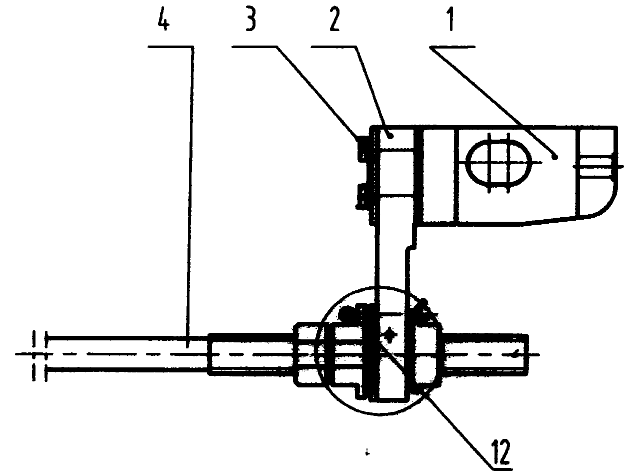
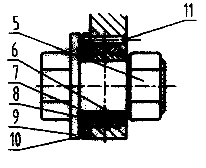
[0015] The embodiment of the point iron of the joint bearing of the present invention will be further described in detail below in conjunction with the accompanying drawings: a point iron of the joint bearing, which is composed of a point iron, a display joint plate, etc., is characterized in that: the point iron 1 and the display joint plate 2 are installed There is a V-shaped insulation 3, indicating that the connection hole of the joint plate 2 has a joint bearing composed of an inner ring 7 and an outer ring 8, and the outer ring 8 is transitionally fitted with the joint plate 2, and a baffle 10 is installed on one side, and the baffle 10 and the The indication joint plate 2 is riveted with rivets 11, and the outer ring 8 is assisted in positioning. The retaining ring 6 is installed on both sides of the outer ring 8, and the shaft sleeve 9 and the nut 5 are installed on both sides of the inner ring 7. The indication rod 4 is adjusted to form a joint bearing. Tip iron. The ...


PUM


Abstract

Knuckle bearing tip iron is suitable for a railway switch mounting device, especially for mounting devices of external locking switches of acceleration, passenger railway lines and heavy load railway lines. The knuckle bearing tip iron comprises a tip iron body, an indication joint plate, an indication pull rod, retaining rings, a knuckle bearing and the like and is characterized in that a V-shaped insulation 3 is disposed between the tip iron body 1 and the indication joint plate 2, the knuckle bearing is mounted at the connecting hole of the joint plate 2, a retaining plate 10 is mounted on one side of the outer ring 8 of the knuckle bearing and riveted to the indication joint plate 2, the retaining rings 6 are mounted on two sides of the outer ring 8, and a shaft sleeve 9 and a nut 5 are mounted on two sides of the inner ring 7. The knuckle bearing tip iron is adaptive to swing during switch rail or point rail telescoping and switching and impact and vibration caused by passing trains. The knuckle bearing tip iron has the advantages that filed mounting and adjusting are facilitated, the insulation structure is free of abrasion and maintenance and long in service life, stress state of rods can be improved, service life of the rods can be prolonged, and deformation of the rods during switch rail or point rail switching is avoided.

Description

technical field [0001] The utility model relates to a point iron of a joint bearing, which is suitable for installation devices of railway turnouts, and is especially suitable for installation devices of externally locked turnouts of speed-increasing, high-speed, and heavy-duty railways. Background technique [0002] The existing railway turnout installation device means that the tie rod is installed on the switch point rail through the tip iron. Due to the crawling of the switch point rail or the center rail and the swing of the point rail and the center rail during the conversion process, it means that the pull rod is subjected to a lateral force, so that the inside of the switch machine The locking rod and indicating rod of the lock rod "open mouth", which leads to the increase of resistance during the switch conversion process and is prone to jamming; the impact of the train wheel pair on the point rail or the center rail, the tip iron and the indicator rod are subjected ...

Claims


Application Information

Patent Timeline
Patent Type & Authority Applications(China)
IPC IPC(8): B61L5/02
Inventor 高国栋周俊伟赵建平王宝松赵永根许剑财阎建忠苏岩
Owner TAIYUAN JINGFENG RAILWAY EQUIP MANUFCTURING CO LTD
Why Eureka
Try Eureka