Novel damping mechanism of engineering water tank

A technology of shock absorption mechanism and water tank, which is applied in the arrangement of cooling combination of power plant, power plant, transportation and packaging, etc., can solve the problem that the connection between the support sleeve heat dissipation equipment and the connecting frame can not provide buffer protection, and the active space of the heat dissipation equipment increases. large, reduce the life of the radiator, etc., to achieve the effect of long-term effect, simple structure and long service life

Inactive Publication Date: 2013-12-18
扬州英谛车材实业有限公司
View PDF0 Cites 0 Cited by
  • Summary
  • Abstract
  • Description
  • Claims
  • Application Information

AI Technical Summary

Problems solved by technology

[0002] Due to the harsh working environment of the radiator used on construction machinery vehicles, the shock absorber needs to be considered in actual use. In the traditional design, the upper end is generally used between the frame and the water tank for shock absorption, and the lower end is only between the water tank and the fixed frame. A rubber support sleeve is added to the connecting part to play the role of shock absorption, but in actual use, due to the tightness of the upper end, the rubber parts at the lower end will bear forces in all directions in actual working conditions. Due to the friction of relative motion, the general rubber parts It is easy to break in a short time, which causes the support sleeve not only to have no buffer protection effect on the connection between the heat dissipation device and the connection frame, but also to increase the activity space of the heat dissipation device at the upper and lower ends of the connection frame due to the rupture of the support sleeve. Large, in harsh working conditions, greatly reducing the life of the radiator

Method used


Image

  • Novel damping mechanism of engineering water tank
  • Novel damping mechanism of engineering water tank
  • Novel damping mechanism of engineering water tank

Examples


Embodiment Construction

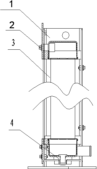
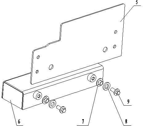
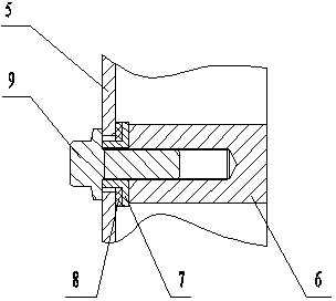
[0014] The new engineering water tank damping mechanism includes an upper connecting part 2 and a lower connecting part 4. The upper connecting part 2 connects and fixes the upper end water chamber 6 of the radiator with the frame 1 through the frame connecting plate 5 of the water tank. The upper connecting part The component 2 includes a connecting bolt 9, a collar rubber pad 8 and a collar iron core 7. The collar rubber pad 8 is set on the collar iron core 7, and the connecting bolt 9 passes through the frame connecting plate 5, The collar rubber pad 8 and the collar iron core 7 are fixed on the water chamber 6 at the upper end of the radiator; the lower connection part 4 is arranged between the support column at the lower end of the radiator 1 and the bottom frame 12, and the lower connection The component 4 is clearance-fitted with the bottom frame 12. The lower connecting component 4 includes a metal attachment sleeve 11 and a shock-absorbing support sleeve 10 nested ther...


PUM


Abstract

The invention relates to a novel damping mechanism of an engineering water tank. The novel damping mechanism comprises an upper connecting assembly and a lower connecting assembly. The upper connecting assembly can fixedly connect a water chamber at the upper end of a radiator with a frame via a frame connecting plate of the water tank; the lower connecting assembly is arranged among a bottom frame and support columns at the lower end of the radiator and is in clearance fit with the bottom frame. The novel damping mechanism has the advantages that the novel damping mechanism is simple in structure and low in manufacturing cost; the water tank is separated from the steel frame by the upper connecting assembly via rubber pads, so that the influence of vibration of the frame on the water tank is reduced under the damping effects of the rubber pads when radiating packs are vibrated; the lower connecting assembly is additionally provided with a metal auxiliary sleeve arranged between a support sleeve and the frame, so that abrasion due to friction is prevented, the service life of the support sleeve is prolonged, and the rubber support sleeve can act for a long time, and the service life of the radiator is prolonged.

Description

technical field [0001] The invention relates to a radiator device for engineering machinery vehicles, in particular to a novel engineering water tank damping mechanism. Background technique [0002] Due to the harsh working environment of the radiator used on construction machinery vehicles, the shock absorber needs to be considered in actual use. In the traditional design, the upper end is generally used between the frame and the water tank for shock absorption, and the lower end is only between the water tank and the fixed frame. A rubber support sleeve is added to the connecting part to play the role of shock absorption, but in actual use, due to the tightness of the upper end, the rubber parts at the lower end will bear forces in all directions in actual working conditions. Due to the friction of relative motion, the general rubber parts It is easy to break in a short time, which causes the support sleeve not only to have no buffer protection effect on the connection bet...

Claims


Application Information

Patent Timeline
Patent Type & Authority Applications(China)
IPC IPC(8): B60K11/04
Inventor 高晓芳牧野张敦虎吴卫槐
Owner 扬州英谛车材实业有限公司
Why Eureka
Try Eureka