Machining center

A machining center and tool technology, applied in the direction of metal processing equipment, metal processing machine parts, manufacturing tools, etc., can solve the problems of rising manufacturing costs, inability to prevent chips, chips and coolant from easily entering the tool warehouse, etc.

Active Publication Date: 2013-12-18
HOWA MASCH LTD
View PDF7 Cites 4 Cited by
  • Summary
  • Abstract
  • Description
  • Claims
  • Application Information

AI Technical Summary

Problems solved by technology

[0005] However, the structure of opening and closing the opening of the tool storage cover with the opening and closing cover described in the above-mentioned Japanese Patent Laid-Open No. 7-112341 leads to an increase in manufacturing cost.
[0006] However, although the structure of providing a rotating cover on the tool holding plate described in Japanese Patent Application Laid-Open No. 2011-45947 can close the opening with a simple structure, it cannot prevent chips from entering the moving area including the pillars provided on the base, etc. non-processing area
In addition, since the opening is large, chips and coolant are easy to enter the tool magazine, and when the tool is replaced, the tool adjacent to the replaced tool (tool installed on the spindle or tool removed from the spindle) Chips, etc. may be attached

Method used


Image

  • Machining center
  • Machining center
  • Machining center

Examples


Embodiment Construction

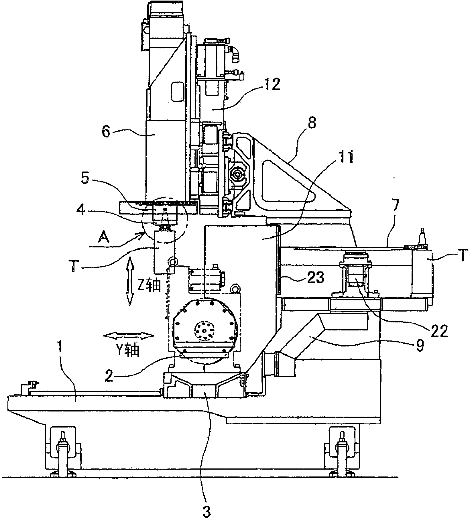
[0030] Specific embodiments of the present invention will be described below with reference to the drawings. figure 1 It shows an example of the machining center of this invention, and is a side view of the state at the time of machining. Reference numeral 1 is a base constituting the base of the machining center, reference numeral 2 is a table on which a workpiece is placed on a slide base 3 described later, reference numeral 3 is a slide base for moving the table 2 in the front-rear direction, Reference numeral 4 is a spindle arranged above the table 2 to rotate the tool T attached thereto, reference numeral 5 is a spindle head supporting the spindle 4, reference numeral 6 is a spindle head lifting body for moving the spindle head 5 up and down, and reference numeral 7 is a spindle head for An armless automatic tool changer (hereinafter referred to simply as an ATC device) that accommodates a plurality of tools T and replaces the tools T mounted on the spindle 4. Reference n...


PUM


Abstract

A shielding plate of a machining center is provided with a back-side plate vertical to a sliding seat and a side-face plate respectively disposed at the left and right of the back-side plate. The back-side plate of the shielding plate is provided with an opening part for a main shaft head and a tool disposed on a main shaft to pass through. A sealing plate for sealing the opening part is disposed between a pair of tool grabbing parts. When machining is conducted on the object, the opening part is sealed by the sealing apparatus so as to isolate the machining area from a non-machining area. When the tool disposed on the main shaft is replaced, the main shaft head passes through the opening part and enters from the machining area into the non-machining area, and then the main shaft will be connected to the tool by the pushed tool grabbing part.

Description

technical field [0001] The present invention relates to a machining center for armless automatic tool changer, and more particularly to a machining center equipped with an armless automatic tool changer on which a workbench for placing a workpiece is placed on a slide seat supported so as to be movable in the Y-axis direction center. Background technique [0002] There is a machining center in which a table on which a workpiece is placed on a slide base supported so as to be movable in the Y-axis direction, and a disk-shaped one having a plurality of tool grips arranged in a ring shape are provided. tool magazine, and make the tool magazine move along the Y-axis direction together with the worktable, so as to perform armless automatic tool replacement (for example, refer to Japanese Patent Laid-Open No. 2008-142891). [0003] On the other hand, among machining centers that perform armless automatic tool change, there is a machining center that has a structure that separates...

Claims


Application Information

Patent Timeline
Patent Type & Authority Applications(China)
IPC IPC(8): B23Q11/00B23Q11/08B23Q3/155
CPCB23Q3/15513B23Q3/15722
Inventor 细川勝也服部一海
Owner HOWA MASCH LTD
Why Eureka
Try Eureka