Micro water fog spray nozzle based on bubble atomization
A technology of micro-water mist nozzles and air bubbles, which is applied in the field of fire extinguishing, micro-water mist nozzles for decontamination, and spray cooling. It can solve the problems of increased manufacturing costs, insufficient spray intensity, and increased system costs to achieve improved safety and good fog. The effect of optimizing and reducing the application cost
- Summary
- Abstract
- Description
- Claims
- Application Information
AI Technical Summary
Problems solved by technology
Method used
Image
Examples
Embodiment 1
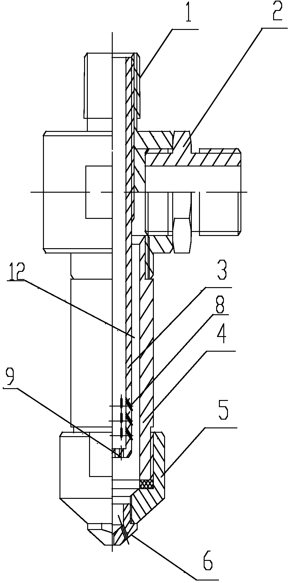
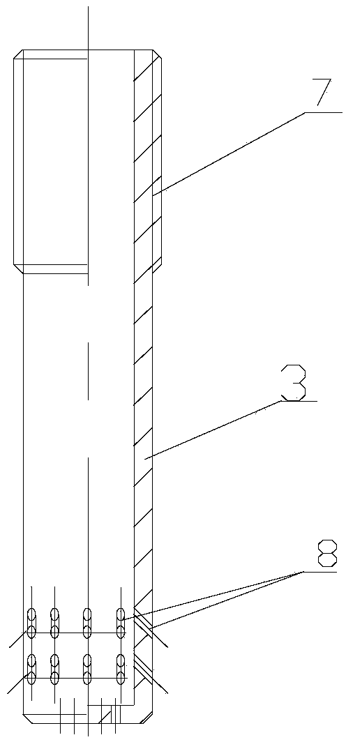
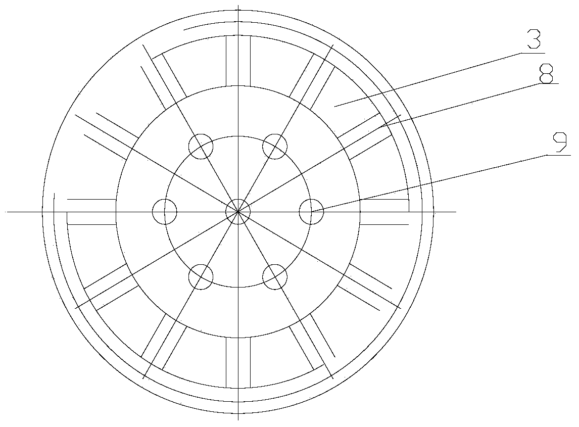
[0016] The structure of the micro-water mist nozzle based on bubble atomization of this embodiment is as follows figure 1 Shown. In the micro-water mist spray head based on bubble atomization of this embodiment, the outside of the spray head is successively a water inlet connector 1, an air inlet connector 2, a sleeve 4, a nozzle cap 5, and a nozzle 6 which are connected to each other by threads; The gas pipe 3 is connected with the water inlet connector 1 by threads, and its end with the gas injection hole 14 is close to the nozzle 6 and forms a mixing chamber 12 with the sleeve 4; the gas injection pipe 3 and the mixing chamber 12 are connected by threads so that the gas injection hole is away from the nozzle The distance can be adjusted; the gas injection pipe 3 is provided with gas injection holes 8, 9; figure 2 It is a half cross-sectional view of the gas injection pipe of the micro water mist nozzle of this embodiment, image 3 It is a cross-sectional view of the double-r...
Embodiment 2
[0019] The structure of the micro-water mist nozzle based on bubble atomization in this embodiment is the same as that of Embodiment 1, except that the structural size of the gas injection pipe changes, mainly referring to the outside diameter of the gas injection pipe, the diameter, number and distribution of the gas injection holes. This embodiment is based on a bubble atomized micro-water mist spray head. The outside of the spray head is followed by a water inlet connector 1, an air inlet connector 2, a sleeve 4, a nozzle cap 5, and a nozzle 6 which are connected to each other by threads; an air injection pipe located inside the nozzle 3 is connected with the water inlet connector 1 by threads, and its end with the gas injection hole 8 is close to the nozzle 6, and forms a mixing chamber 12 with the sleeve 4; the gas injection pipe 3 and the mixing chamber 12 are connected by threads so that the distance between the gas injection hole and the nozzle Adjustable; the gas inject...
PUM
 Abstract
Description
Claims
Application Information
 - Generate Ideas
- Intellectual Property
- Life Sciences
- Materials
- Tech Scout
- Unparalleled Data Quality
- Higher Quality Content
- 60% Fewer Hallucinations
Browse by: Latest US Patents, China's latest patents, Technical Efficacy Thesaurus, Application Domain, Technology Topic, Popular Technical Reports.
© 2025 PatSnap. All rights reserved.Legal|Privacy policy|Modern Slavery Act Transparency Statement|Sitemap|About US| Contact US: help@patsnap.com


