Rolling-element bearing cage and method for producing a rolling-element bearing cage

A technology for rolling bearings and cages, which is applied to rolling contact bearings, bearings for rotational motion, bearings, etc., can solve problems such as mechanical weakening of cage connecting beams, and achieve the effect of improving bearing capacity

Active Publication Date: 2013-12-11
SCHAEFFLER TECH AG & CO KG
View PDF9 Cites 3 Cited by
  • Summary
  • Abstract
  • Description
  • Claims
  • Application Information

AI Technical Summary

Problems solved by technology

The disadvantage of this back milling is that the cage connection beam is mechanically weakened at the transition to the side edge or side ring due to the back milling

Method used


Image

  • Rolling-element bearing cage and method for producing a rolling-element bearing cage
  • Rolling-element bearing cage and method for producing a rolling-element bearing cage
  • Rolling-element bearing cage and method for producing a rolling-element bearing cage

Examples


Embodiment Construction

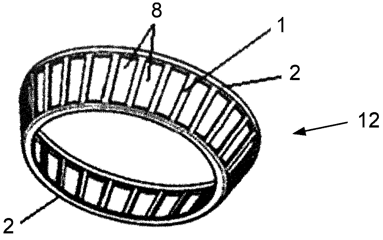
[0034] figure 1 Shown is a rolling bearing cage 12 constructed according to the invention, which is milled out of a ring-shaped solid part. A multi-axis milling machine is used for this, which mills out the cage pockets 8 so that the side rings 2 are fixedly coupled to one another via a plurality of cage connecting beams 1 .

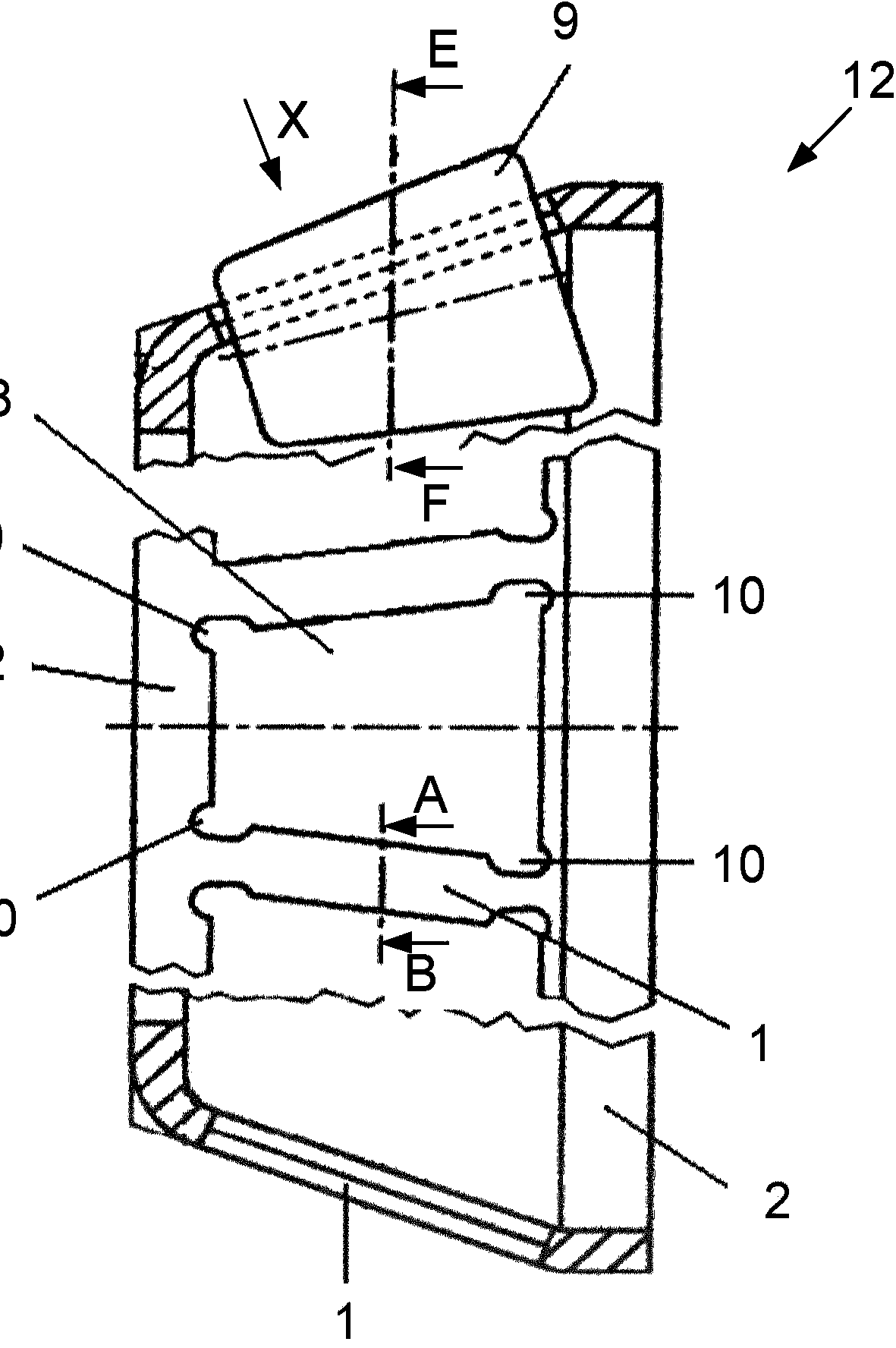
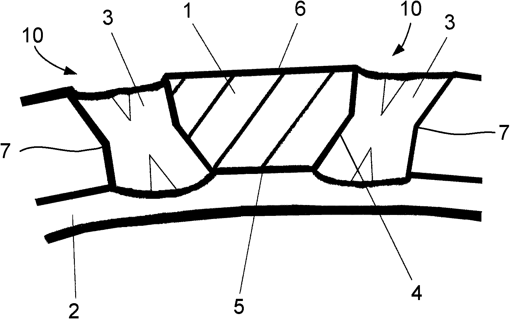
[0035] Rolling bearing cage 12 can be found in figure 2 It is clearly seen in the longitudinal section of the . The conical rolling bodies 9 are inserted into the cage pockets 8 , which in a known manner pass through the cage pockets 8 with only a part of their diameter. in sight Figure X The fully visible cage pocket 8 shown in , has pocket corners 10 that can be considered partially elliptical or partially sports-field-like in the region where the cage connecting beam 1 is connected to the two side rings 2 . These pocket corners 10 are shaped and in particular radially formed in such a way that the rolling bodies accommodated in the cage pockets ...


PUM


Abstract

The invention relates to a rolling-element bearing cage (12) comprising two lateral rings (2) and a plurality of cage webs (1), wherein the laterals rings (2) and the cage webs (1) form a plurality of cage pockets (8). In order for said rolling-element bearing cage (12) to have an especially light and stable design, according to the invention a respective recess (3) is formed in each of the corners (10) of the cage pockets (8). Said recess is tapered or reduced toward the radial center (7) of the recess without forming a running surface for the associated rolling element (9). The invention further relates to a method for producing the rolling-element bearing cage (12) according to the invention, wherein a plurality of cage pockets (8) are milled into a solid cage blank, wherein the corners (10) of the cage pockets (8) are milled in such a way that a respective recess (3) is formed in each of the corners of the cage pockets, which recess is tapered or reduced toward the radial center (7) of the recess without forming a running surface for the associated rolling element (9).

Description

technical field [0001] The invention relates to a rolling bearing cage with two side rings and a plurality of cage connecting beams, wherein the side rings and the cage connecting beams form a plurality of cage pockets. Furthermore, the invention relates to a method for producing such a rolling bearing cage. Background technique [0002] Rolling bearing cages of the aforementioned type (eg for tapered roller bearings) are produced from a ring-shaped cage blank, the contours for the cage pockets being milled out. The contour of the cage cavity is determined as far as possible according to the type and size of the rolling elements used. In the case of conical or cylindrical rolling elements, the cage pockets have an approximately quadrangular contour. Recesses are usually milled into the corners of the cage pockets which prevent the rolling bodies from abutting against the corners of the cage pockets. For example, DE 10021089 B4 describes a cage for a rolling bearing, in wh...

Claims


Application Information

Patent Timeline
Patent Type & Authority Applications(China)
IPC IPC(8): F16C33/46
CPCF16C33/4623F16C2220/66F16C19/364Y10T409/303752F16C33/467B23C3/02
Inventor 亚历山大·舒尔茨
Owner SCHAEFFLER TECH AG & CO KG
Why Eureka
Try Eureka