Camera image resolution estimation method and camera image resolution estimation system

A technology for image clarity and clarity evaluation, which is applied in image communication, television, electrical components, etc., can solve problems such as human eye judgment obstacles, display, visual fatigue, etc., to improve product consistency, improve focusing efficiency, reduce eye strain effect

Inactive Publication Date: 2013-12-11
SOUTH CHINA UNIV OF TECH
View PDF2 Cites 21 Cited by
  • Summary
  • Abstract
  • Description
  • Claims
  • Application Information

AI Technical Summary

Problems solved by technology

[0003] At present, the focusing of the camera module is still done manually. The image acquisition circuit is connected to the camera, and the image data is collected from the camera module and transmitted to the PC for display. Workers judge the current camera lens according to the image clarity within the field of view of the camera. Whether to achieve the ideal focusing distance, although the manual focusing method can meet the production requirements of the factory, there are also disadvantages; first, the daily output of camera modules is large, and workers who repeatedly observe the stripes of the focused image are prone to visual fatigue
Secondly, because workers have different evaluations on the clarity, each worker has a different grasp of the clear position of the camera module focusing, which makes it difficult to ensure the consistency of product clarity. Finally, as the pixel size of the produced product increases, It is difficult for the computer display screen to display the entire field of view, which hinders the judgment of the human eye

Method used


Image

  • Camera image resolution estimation method and camera image resolution estimation system
  • Camera image resolution estimation method and camera image resolution estimation system
  • Camera image resolution estimation method and camera image resolution estimation system

Examples


Embodiment 1

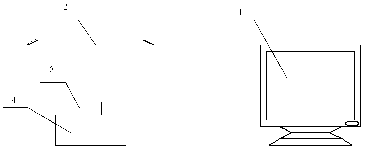
[0029] Such as figure 1 As shown, an evaluation system for realizing the camera image definition evaluation method includes: PC 1 (the upper computer in this embodiment adopts PC) and module data acquisition module 4, PC 1 and module data acquisition module 4 Connected by connecting wire; standard for adjusting focus figure 2 Separately placed directly in front of the module, and, the standard figure 2 The specific location of placement is determined according to the different models of the modules; the camera module 3 is electrically connected to the module data acquisition module 4.

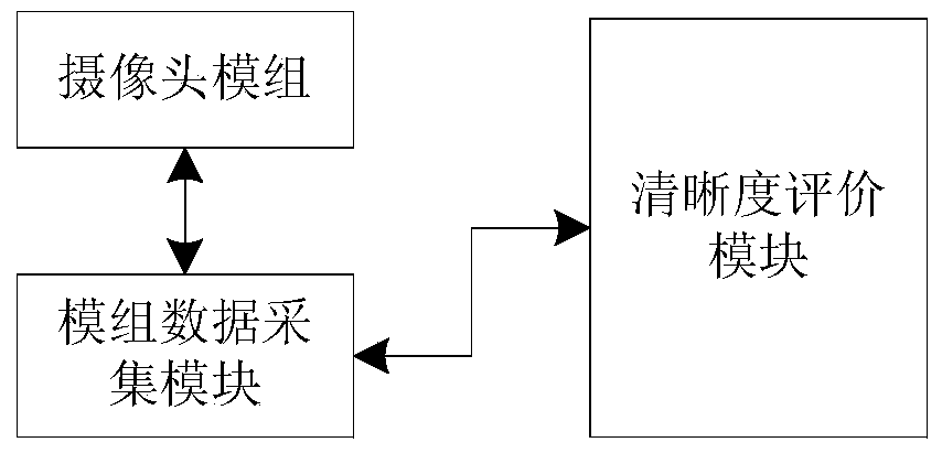
[0030] The data transmission relationship of the system is as follows: figure 2 As shown, the camera module is connected to the module data collection module, and the module data collection module is connected to the definition evaluation module.

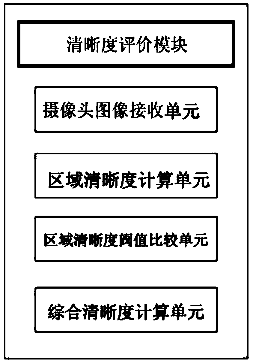
[0031] The block diagram of the clarity evaluation module is as follows: image 3 As shown, the host computer 1 includes a camera sharpness e...

Embodiment 2

[0045] This embodiment is the same as Embodiment 1 except for the following:

[0046] The upper computer in this embodiment adopts an embedded system.


PUM


Abstract

The invention discloses a camera image resolution estimation system which comprises a camera module, a standard image, an upper computer, a resolution estimation module and a module data collecting module. The invention further discloses an estimation method of the camera image resolution estimation system. The estimation method comprises the steps that (1) the camera module is connected with the module data collecting module; (2) the module data collecting module is provided with a camera and a camera image is read into a cache area; (3) the camera image is transmitted to a memory of the resolution estimation module from the cache area of the module data collecting module through a data line; (4) if a camera resolution estimation value is larger than a set resolution threshold, the resolution estimation module sends the signal that the focus of the camera is adjusted to the required resolution degree; (5) the resolution estimation module estimates the resolution of the image, and the user adjusts the position of a lens according to a display result. The camera image resolution estimation system has the advantages of being intelligent, high in efficiency, high in accuracy and the like.

Description

technical field [0001] The present invention relates to an optical camera image definition evaluation technology, in particular to a camera image definition evaluation method and evaluation system thereof. The present invention collects image data from an optical camera sensor through a circuit module, and evaluates the camera definition. Background technique [0002] The cameras targeted by the present invention are mainly built-in camera modules applied to digital products such as mobile phones. Most of these cameras do not have an optical zoom function, are simple in structure, and have a deep depth of field. In actual production, after the camera is assembled, , Before leaving the factory, it is necessary to adjust the focal length and fix the lens so that the camera can produce clear images in actual work. Since there are many sensor models of the camera, and the camera lens needs to have a relatively accurate focal length to ensure the image of the camera module Clarit...

Claims


Application Information

Patent Timeline
Patent Type & Authority Applications(China)
IPC IPC(8): H04N17/00
Inventor 黄茜汤达浚
Owner SOUTH CHINA UNIV OF TECH
Why Eureka
Try Eureka