Electromagnetic relay with flexible coupling mechanism

A technology of electromagnetic relay and flexible connection, which is applied in the direction of electromagnetic relay, electromagnetic relay details, relay, etc. It can solve problems such as unstable rigid force, armature and yoke cannot be reliably engaged, and the damage of the tripping mechanism is small.

Active Publication Date: 2015-08-19
SHANGHAI NOARK ELECTRIC
View PDF6 Cites 0 Cited by
  • Summary
  • Abstract
  • Description
  • Claims
  • Application Information

AI Technical Summary

Problems solved by technology

[0004] In order to overcome the above-mentioned defects in the prior art, the object of the present invention is to provide an electromagnetic relay with a flexible coupling mechanism. The stable impact force becomes a flexible force that is not affected by the size of the external force. Through the flexible action of the push plate spring in the output repulsive force, not only the unstable rigid force output by the original ejector rod becomes stable, which is beneficial to the tripping action of the circuit breaker Stable flexible force, and the force that reacts on the push plate is also changed into a flexible force. Through the flexible action of the lever spring in the process of energy storage and release, the buffering of the output impact force of the ejector rod is realized, which can not only produce the required tripping force. Large operating force, and less damage to the tripping mechanism, thus solving the problem of wear, deformation and motion accuracy failure of the armature and related moving parts caused by the frequent and excessive impact force of the ejector rod, so that the armature and related moving parts are free from damage. It is damaged by impact, and at the same time, it also solves the problem that the armature and the yoke cannot be reliably engaged due to the deformation of the air gap between the armature and the yoke, which is beneficial to prolong the effective life of small electromagnetic relays and circuit breakers

Method used


Image

  • Electromagnetic relay with flexible coupling mechanism
  • Electromagnetic relay with flexible coupling mechanism
  • Electromagnetic relay with flexible coupling mechanism

Examples


Embodiment Construction

[0026] The specific implementation of the electromagnetic relay with flexible coupling mechanism of the present invention will be described in detail below with reference to the embodiments given in the accompanying drawings. The electromagnetic relay with flexible coupling mechanism of the present invention is not limited to the description of the following embodiments.

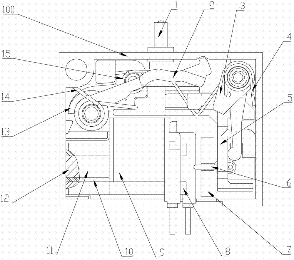
[0027] figure 1 It is a schematic diagram of the overall structure of an embodiment of the electromagnetic relay with a flexible coupling mechanism of the present invention. The electromagnetic relay with a flexible coupling mechanism of the present invention includes a fixed plate 13 fixedly installed in the housing 100, a push rod 1 operably installed on the housing 100 by external force, and a magnetic relay fixedly installed in the housing 100. Yoke 8 and the armature 7, electromagnetic coil 9, separator 10, magnetic plate 11 and permanent magnet 12 that are engaged / disengaged with the magnetic yoke 8, ...


PUM


Abstract

The electromagnetic relay with a flexible coupling mechanism includes a push rod, an armature, and a flexible coupling mechanism arranged between the push rod and the armature. It includes a lever and a lock that are respectively pivotally installed in the housing. The fixed shaft rotates to realize the snap connection of locking / separation. The flexible coupling mechanism also includes a push plate movably installed on the fixed plate. The spring of the push plate is elastically connected to the lever. The elastic linkage connection makes the push plate reciprocate in a straight line under the action of the push plate spring and the lock. The armature is installed on the push plate through the connection structure, the two are linked with each other, the ejector rod is connected with the lever, the tripping output force of the ejector rod is provided by the spring, and the lock spring provides the lock to act on the push plate along its moving direction The direction of the pushing force Q is opposite to the elastic force P of the push plate spring acting on the push plate along its moving direction, so as to achieve reliable engagement between the armature and the yoke or avoid the impact force output by the ejector rod.

Description

technical field [0001] The invention relates to the field of low-voltage electrical appliances, in particular to the field of low-voltage circuit breakers, in particular to an electromagnetic relay suitable for residual current operated circuit breakers. Background technique [0002] In the field of low-voltage electrical appliances, the electromagnetic relay that uses a weak current signal as the excitation current is actually an electromagnetic actuation device in the trip control circuit. It is often used in residual current operated circuit breakers, circuit breakers with shunt tripping functions or electronic tripping in the circuit breaker of the device. For example, the electromagnetic relay (EMR), as an internal component of the electromagnetic residual current operated circuit breaker, is used to trigger the mechanical structure after receiving the weak current signal, and can convert the weak current signal into a mechanical action that controls the tripping of the...

Claims


Application Information

Patent Timeline
Patent Type & Authority Patents(China)
IPC IPC(8): H01H50/30H01H50/64
Inventor 严鹏斌邓彦军应威
Owner SHANGHAI NOARK ELECTRIC
Why Eureka
Try Eureka