
Handheld dynamic light wave diffraction demonstration instrument

A demonstration instrument, a handheld technology, applied in the field of hand-held dynamic light wave diffraction demonstration instrument, can solve the problems of inconvenient to carry, bulky, bulky instrument volume, etc., and achieve the effect of easy promotion, simple structure and easy portability

Active Publication Date: 2013-12-11
TIANJIN YIYANG HUARUI TECH CO LTD
View PDF12 Cites 15 Cited by
  • Summary
  • Abstract
  • Description
  • Claims
  • Application Information

AI Technical Summary

Problems solved by technology

[0003] At present, there are many optical instruments, but they are bulky and bulky, inconvenient to carry, and require relatively high experimental environmental conditions, such as low light conditions; at the same time, laboratory demonstration teaching cannot guarantee students' experimental results. The progress is the same as that of the theory class, so as to achieve the organic combination of theory and practice
As far as light wave diffraction is concerned, the existing small hand-held experimental instrument (handheld wave optics demonstrator, patent number: ZL200820122697.X) cannot simultaneously display the diffraction phenomenon of two beams of light waves with different wavelengths, and cannot dynamically test the diffraction fringes when the width of a single slit changes continuously. The changing law of the model can only be demonstrated qualitatively, and cannot be measured and calculated quantitatively to verify the theoretical results

Method used


Image

  • Handheld dynamic light wave diffraction demonstration instrument
  • Handheld dynamic light wave diffraction demonstration instrument
  • Handheld dynamic light wave diffraction demonstration instrument

Examples


Embodiment Construction

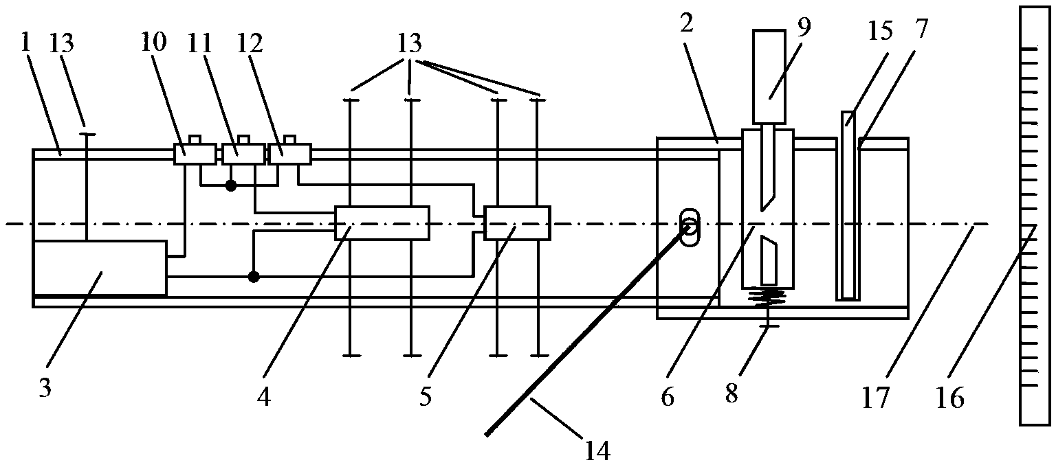
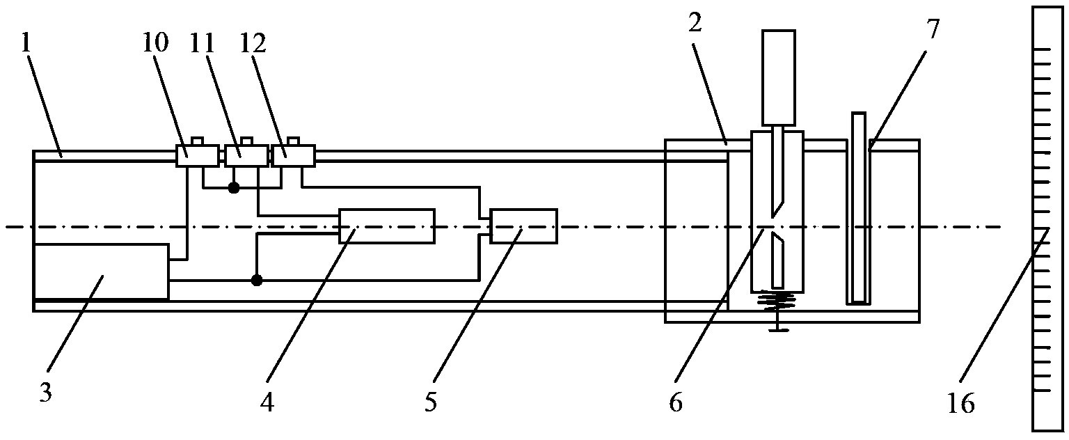
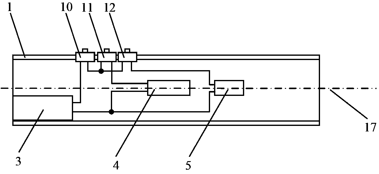
[0029] The structure of the handheld dynamic light wave diffraction demonstration instrument of the present invention is described in conjunction with the accompanying drawings.

[0030] The structure of the handheld dynamic light wave diffraction demonstration instrument of the present invention is that the demonstration instrument includes organic glass tube A1 and organic glass tube B2 which are rotatably socketed with each other, and also includes a power supply box 3, a green laser 4, a red laser 5, and Adjust slit device 6, grating slot 7, measuring scale 16 and main switch 10, red light switch 11, green light switch 12.

[0031] The power supply box 3 is connected with the main switch 10 through the output wire, the main switch 10 is connected with the green laser 4 through the green light switch 11, the red light laser 5 is connected with the red light switch 12, the power supply box 3, the green light laser 4, The red laser 5 is fixed in the plexiglass tube A1 by the ...


PUM


Abstract

The invention provides a handheld dynamic light wave diffraction demonstration instrument. The handheld dynamic light wave diffraction demonstration instrument comprises an organic glass tube A and an organic glass tube B which are mutually and rotatably connected in a sleeved mode, and further comprises a power pack, a green laser, a red laser, an adjustable slit device, an optical grating location slot, a measuring ruler, a main switch, a red light switch and a green light switch. Two pairs of holes are respectively formed in the sleeved connection position of the organic glass tube A and the organic glass tube B, the two pairs of holes are symmetrically formed, the axis of the two pairs of holes is parallel to the slit direction of the adjustable slit device, and the two ends of an instrument support are inserted into the holes. The measuring ruler is arranged on one side of the organic glass tube B, and light beams of the green laser and light beams of the red laser are projected to the measuring ruler. The handheld dynamic light wave diffraction demonstration instrument has the advantages of being small and exquisite in size, convenient to carry, capable of being used for classroom teaching directly, and convenient and flexible to use due to the fact that a dark area in a classroom can be chosen as the background to conduct demonstration, quantitative measurement can also be achieved, and the measuring ruler can be directly attached to a blackboard through build-in magnetism conveniently.

Description

technical field [0001] The invention relates to a teaching instrument, in particular to a hand-held dynamic light wave diffraction demonstration instrument. Background technique [0002] Optics is an important part of college physics courses. The diffraction characteristic of light is an important knowledge point of the optics part. Since this characteristic is not easy to be understood by students who are in the initial contact, it is considered to promote students' understanding and mastery through live and intuitive classroom experiment demonstrations The diffraction characteristics of light can improve the teaching effect of college physics courses. [0003] At present, there are many optical instruments, but they are bulky and bulky, inconvenient to carry, and require relatively high experimental environmental conditions, such as low light conditions; at the same time, laboratory demonstration teaching cannot guarantee students' experimental results. The progress is th...

Claims


Application Information

Patent Timeline
IPC IPC(8): G09B23/22
Inventor 杨广武江越朱飞刘枝朋金光浩
Owner TIANJIN YIYANG HUARUI TECH CO LTD
Learn More