Intake manifold performance testing device and testing method

An intake manifold and detection device technology, which is applied in the fields of intake manifold performance detection and intake manifold performance detection device, can solve the problems of irregularity, inconsistent influence, complicated operation, etc.

Active Publication Date: 2016-05-04
GREAT WALL MOTOR CO LTD
View PDF7 Cites 0 Cited by
  • Summary
  • Abstract
  • Description
  • Claims
  • Application Information

AI Technical Summary

Problems solved by technology

However, for the detection of the performance of the intake manifold, at this stage, CFD analysis is only carried out theoretically, and there is no method for testing and testing the intake manifold entity alone.
[0004] Theoretical CFD analysis on the performance of the intake manifold has unavoidable drawbacks because it cannot be tested whether the entity of the intake manifold is completely consistent with the digital model.
For example, when performing CFD analysis on the intake manifold, it is assumed that each branch of the intake manifold has the same effect on the gas flow of each cylinder, but the actual processed intake manifold is installed on the cylinder head for testing At this time, the influence of each branch of the intake manifold on each cylinder is inconsistent, and there is no certain rule, and when the intake manifold is installed on the cylinder head for test detection, the operation is very complicated, and it cannot be used when the detection value fluctuates greatly. Determine whether it is the problem of the intake manifold or the shape of the air passage of the cylinder head itself. This will cause great trouble to trace the problem, and also increase the difficulty in the development and testing of the intake manifold.

Method used


Image

  • Intake manifold performance testing device and testing method
  • Intake manifold performance testing device and testing method
  • Intake manifold performance testing device and testing method

Examples


Embodiment 1

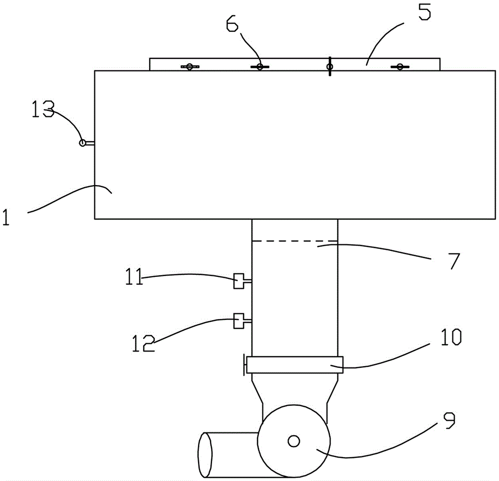
[0033] This embodiment relates to an intake manifold performance detection device, which is Figure 1 to Figure 3 As shown, it includes a surge chamber 1, a manifold connecting plate 5 arranged on the upper surface of the surge chamber 1, and an outlet pipe 7 arranged on the lower surface of the surge chamber 1, which is connected to the surge chamber 1 in the outlet pipe 7 A vortex generator 8 is provided at the air outlet pipe 7, and a vacuum fan 9 is connected to the end of the air outlet pipe 7. A valve 10 for controlling the opening and closing of the air outlet pipe 7 is arranged on the air outlet pipe 7 close to the vacuum fan 9, and the air outlet pipe 7 is provided with The vortex flow meter 11 and the flow meter 12 for detecting the gas in the gas outlet pipe 7 are also provided with a vacuum gauge 13 for detecting the internal vacuum degree of the surge chamber 1.

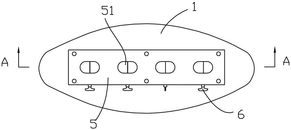
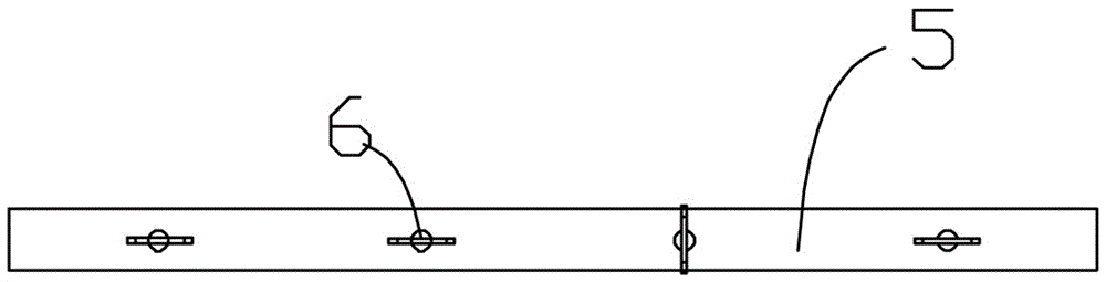
[0034] The structure of the manifold connecting plate 5 is as Figure 4 with Figure 5 As shown, it is a ...

Embodiment 2

[0038] This embodiment relates to a method for detecting the performance of an intake manifold. The method includes the following steps:

[0039] Step a, all control valves 6 are rotated to the closed state, and the vacuum fan 9 is turned on to vacuum the pressure-stabilizing chamber 1, when the vacuum gauge 13 shows that the vacuum degree reaches 10KPa, the valve 10 is closed, and the pressure-stabilizing chamber is allowed to stand for a period of time. 1 tightness;

[0040] Step 1: Open one of the control valves 6 so that the airflow in the branch of the intake manifold corresponding to the control valve 6 enters the surge chamber 1;

[0041] Step 2: When the airflow in the surge chamber 1 is discharged from the air outlet pipe 7, the vortex generator 8 converts the airflow into a vortex;

[0042] Step 3: The vortex flow meter 11 and the flow meter 12 are used to detect the lightness and flow rate of the vortex formed in the outlet pipe 7 respectively;

[0043] Step four, repeat ste...


PUM


Abstract

The invention relates to a performance detection device and a detection method of an intake manifold. The connecting hole connected with the pipe and communicated with the hollow cavity, the control valve for opening and closing the connecting hole is arranged on the manifold connecting plate, and the air outlet pipe is fixedly arranged outside the pressure stabilizing chamber and communicated with the hollow cavity , the outlet pipe is equipped with a vortex generating device that converts the gas flowing out of the plenum chamber into a vortex, a vortex flow meter and a flow meter that detect the strength and flow of the vortex, and a gas discharge that is fixed at the free end of the outlet pipe. device. The device can be used to detect the influence of each branch of the intake manifold on the air flow of each cylinder, and realize the combination of theoretical analysis and actual test of the intake manifold, so as to have a reasonable and accurate evaluation of the performance of the intake manifold.

Description

technical field [0001] The invention relates to a detection device, in particular to a performance detection device of an intake manifold, and also relates to a performance detection method of an intake manifold. Background technique [0002] The airflow movement in the gasoline engine cylinder has an important influence on the combustion process of the engine, especially the structure of the flow field in the cylinder at the end of the intake air, which will directly determine the turbulence intensity, airflow velocity near the spark plug at the ignition moment, and the distribution of fuel in the cylinder, thus It affects the power, economy and emission of the engine, which puts forward requirements on the performance parameters of the intake port and intake manifold. [0003] At present, there are mainly two methods for testing the performance of the air inlet, the steady state test using the air passage steady flow test bench, and the CFD digital-analog analysis. Howeve...

Claims


Application Information

Patent Timeline
Patent Type & Authority Patents(China)
IPC IPC(8): G01M13/00
Inventor 杜更理高小明张卫刘克明
Owner GREAT WALL MOTOR CO LTD
Why Eureka
Try Eureka