
Roller bracket

A technology of rollers and support plates, applied in the direction of rigid brackets of bearing components, bearing elements, shafts and bearings, etc., can solve the problems of inconvenience and increased structural complexity, and achieve remarkable effects, compact structure and reasonable design

Inactive Publication Date: 2013-12-11
黄平
View PDF8 Cites 0 Cited by
  • Summary
  • Abstract
  • Description
  • Claims
  • Application Information

AI Technical Summary

Problems solved by technology

[0002] The existing roller brackets directly insert the rollers on the brackets, and the rotation speed of the rollers needs to be adjusted by other equipment, which increases the complexity of the structure and is extremely inconvenient

Method used


Image

  • Roller bracket

Examples


Embodiment Construction

[0011] In order to make the technical means, creative features, goals and effects achieved by the present invention easy to understand, the present invention will be further described below in conjunction with specific illustrations.

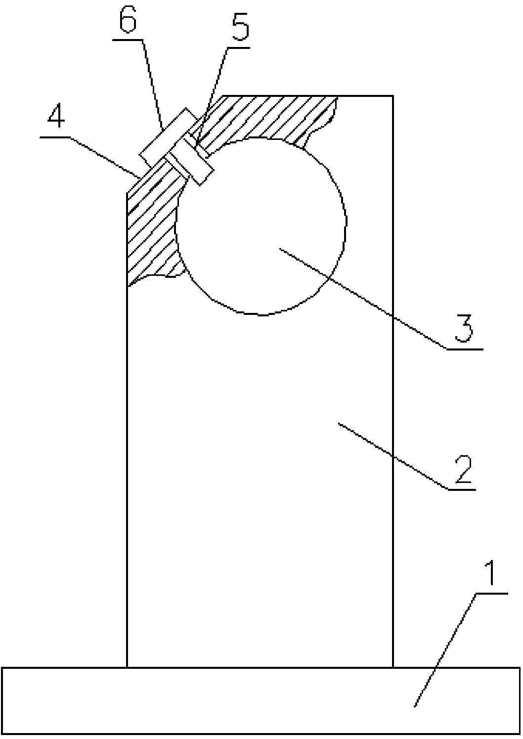
[0012] Such as figure 1 The shown roller bracket includes a base plate 1, a support plate 2 is provided on the base plate 1, a hole 3 is provided on the support plate 2, and a trimming edge 4 is cut on the upper end of the supporting plate 2, and the slope of the trimming edge 4 is 45° , trimming 4 is provided with threaded hole 5, and threaded hole 5 leads in the hole 3, is provided with screw 6 in the threaded hole 5, and threaded hole 5 is vertical with trimming 4, and threaded hole 5 is located at the center of trimming 4.

[0013] The basic principles, main features and advantages of the present invention have been shown and described above. Those skilled in the industry should understand that the present invention is not limited by the ab...


PUM


Abstract

The invention discloses a roller bracket and relates to a bracket. The roller bracket comprises a bottom plate, wherein a support plate is arranged on the bottom plate, and a hole is formed in the support plate. The roller bracket is characterized in that a trimming edge is cut at the upper end of the support plate; a gradient of a bevel edge of the trimming edge is 45 degrees; a threaded hole is formed in the trimming edge, and led into the hole; and a screw is arranged in the threaded hole. The roller bracket is simple in structure, reasonable in design, simple, practical, compact in structure and significant in effect; a spindle in the hole is adjusted to rotate by the tightness of the screw; and the screw is mounted on the trimming edge, so that the problem that an object is hung frequently due to the fact that the prior screw is mounted at the top is solved.

Description

Technical field: [0001] The invention relates to a bracket, in particular to a roller bracket. Background technique: [0002] In the existing roller brackets, the rollers are directly inserted into the brackets, and the rotation speed of the rollers needs to be adjusted by other equipment, which increases the complexity of the structure and is extremely inconvenient. Invention content: [0003] The technical problem to be solved by the present invention is to overcome the defects of the prior art and provide a roller bracket with a compact structure and good speed regulation effect. [0004] The technical problem to be solved by the present invention is realized by the following technical solutions. [0005] A roller bracket, comprising a base plate, a support plate is provided on the base plate, and a hole is provided on the support plate, and it is characterized in that: the top of the support plate is cut with a cut edge, and the slope of the cut edge is 45°. Threaded...

Claims


Application Information

Patent Timeline
Patent Type & Authority Applications(China)
IPC IPC(8): F16C35/08
Inventor 黄平
Owner 黄平
Learn More