Curtain structure using tensioner

A technology of tensioner and curtain, which is applied to the devices used in theaters, circuses, etc., entertainment, stage devices, etc. It can solve the problems of short service life of the curtain structure, wrinkles of the curtain A1, water and dust accumulation on the curtain, etc., and achieve waterproof effect Improvement, fast installation speed, and the effect of reducing the gray level of water accumulation on the roof structure

Active Publication Date: 2015-05-06
ZHEJIANG BAOYE CONSTR GROUP CO LTD
View PDF5 Cites 0 Cited by
  • Summary
  • Abstract
  • Description
  • Claims
  • Application Information

AI Technical Summary

Problems solved by technology

Its disadvantages are: 1. Each of its curtain lock edge clamps A3 only clamps a part of the edge of the curtain A1, which is easy to cause wrinkles on the surface of the curtain A1, and at the same time shortens the service life of the curtain structure
2. It is very troublesome to install and needs to fix multiple bolts A33
3. It does not use tension to tighten the curtain A1, so that the curtain is not smooth enough, and it is easy to accumulate water and dust on the curtain, that is to say, the curtain has a concave part, and the concave part is easy to accumulate water and dust

Method used


Image

  • Curtain structure using tensioner
  • Curtain structure using tensioner
  • Curtain structure using tensioner

Examples


Embodiment

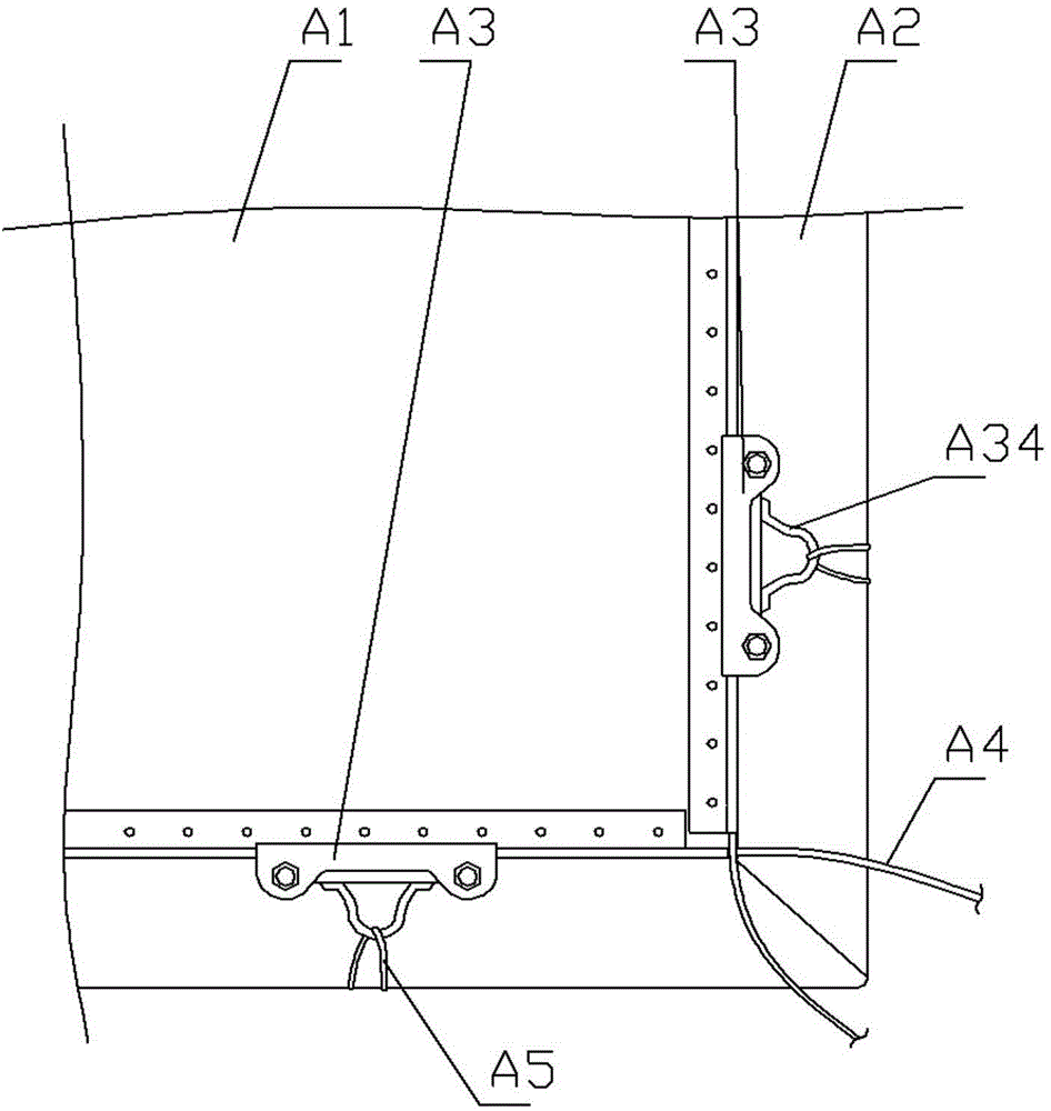
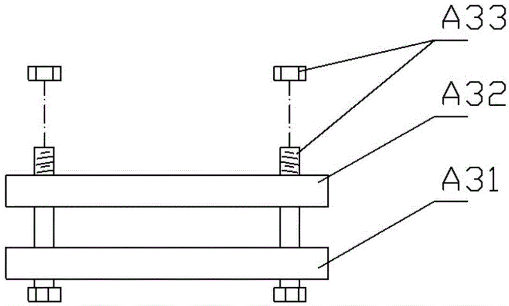
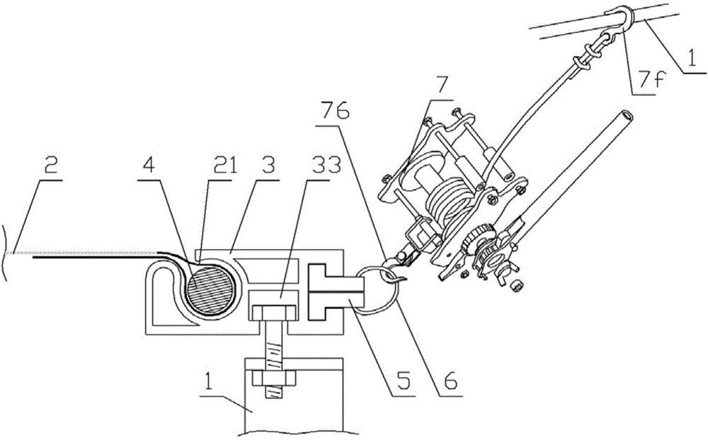
[0025] Example: see Figures 3 to 8 As shown, a curtain structure using a tensioner includes a curtain structure bracket 1 and a curtain 2. The structure of the overlock bead 3 is that a circular groove 32 with an upper opening 321 is formed on the plate body 31, and is located on the plate body 31. The lower T-shaped groove 33 of the bottom and the right T-shaped groove 34 positioned at the right part of the plate body 31, the cross-section of the lower T-shaped groove 33 is "T" and the opening of the groove is downward, and the cross-section of the right T-shaped groove 34 is "T" shape and slot opening to the right;

[0026] The curtain 2 has a curtain buckle lap 21, the buckle rubber strip 4 is put on the curtain buckle lap 21, the curtain buckle lap 21 is inserted into the circular groove 32, and the lower T-shaped groove 33 is inserted into the curtain structure On bracket 1;

[0027] The structure of the pull block 5 is that it is an "L"-shaped plate body composed of a...


PUM


Abstract

The invention discloses a curtain structure using a tensioner. A lock edge pressure strip is structurally characterized in that a round groove with an upper opening, a lower T-shaped groove at the lower part of a plate body and a right T-shaped groove at the right part of the plate body are formed in the plate body, the lower T-shaped groove is provided with a T-shaped cross section and a downward opening, and the right T-shaped groove is provided with a T-shaped cross section and a rightward opening; a curtain is provided with a curtain buckle edge lap, a buckle edge rubber strip is sleeved on the curtain buckle edge lap in a penetration way, the curtain buckle edge lap is inserted and sleeved in the round groove, and the lower T-shaped groove is inserted and sleeved on a curtain structure bracket; each pull block is an L-shaped plate body comprising a short edge and a long edge, a through hole is formed in the long edge, and the height of the short edge is smaller than the width of the opening of the right T-shaped groove; two pull blocks are stacked, inserted and sleeved in the right T-shaped groove, and a pull rope is sleeved in the through holes in the penetration way; a suspension hook is suspended on the curtain structure bracket, and the pull rope is pulled by a pull hook 76. According to the curtain structure, the curtain tension force is balanced, the curtain is smooth, the service life of the curtain structure is prolonged, and the effect of lightly lifting the curtain due to airflow and wind is remarkably reduced.

Description

Technical field: [0001] The invention relates to the technical field of construction, and more specifically relates to a curtain structure using a tensioner. Background technique: [0002] See figure 1 , 2 As shown, the existing curtain structure is composed of a curtain A1, a curtain bracket A2 and a curtain lock clamp A3, a rope A4 is fixed on the side of the curtain A1, the curtain lock clamp A3 clamps the rope A4, and the curtain lock clamp A3 passes through a steel wire or Iron wire A5 is fixed on the curtain support A2. Curtain lock edge clamp A3 is composed of upper clamping block A31, lower clamping block A32 and bolt A33, upper clamping block A31 and lower clamping block A32 are fixed together by bolt A33, lower clamping block A32 is formed with fixed ear A34, steel wire or iron wire A5 is fastened on the fixed ear A34. Its disadvantages are: 1. Each of its curtain lock edge clamps A3 only clamps a part of the edge of the curtain A1, which easily causes the surf...

Claims


Application Information

Patent Timeline
Patent Type & Authority Patents(China)
IPC IPC(8): A63J1/02
Inventor 孙永明倪华君俞国方娄忠华王荣标傅伟东王光梅
Owner ZHEJIANG BAOYE CONSTR GROUP CO LTD
Why Eureka
Try Eureka