
Cell Clamping Mechanism

A battery clip and battery cell technology, which is applied in the manufacture of secondary batteries, non-aqueous electrolyte batteries, electrolyte batteries, etc., can solve the problems of low winding efficiency of flat batteries and uneven tension of winding flat batteries. Achieve the effect of avoiding low winding efficiency, avoiding uneven tension, and improving winding efficiency

Active Publication Date: 2018-07-13
CONTEMPORARY AMPEREX TECH CO
View PDF8 Cites 0 Cited by
  • Summary
  • Abstract
  • Description
  • Claims
  • Application Information

AI Technical Summary

Problems solved by technology

[0005] The purpose of the present invention is to overcome the deficiencies in the prior art, to provide a cell clamping mechanism, to flatten the circular cell to obtain a flat cell, to avoid the low winding efficiency of the flat cell in the prior art, and There is a problem of uneven tension around the flat battery core, which improves the quality of the battery core

Method used


Image

  • Cell Clamping Mechanism
  • Cell Clamping Mechanism
  • Cell Clamping Mechanism

Examples


Embodiment Construction

[0026] The present invention will be further described below in conjunction with specific drawings.

[0027] The directions or positional relationships such as "left, right" and "front and back" proposed in the present invention are based on the attached figure 1 The orientation or positional relationship shown, the "left and right" proposed in the present invention refers to the attached figure 1 as a benchmark, figure 1 The left side of is "Left", figure 1 The right side of is "Right", figure 1 The direction facing the paper is "front", and the direction of the back paper is "rear".

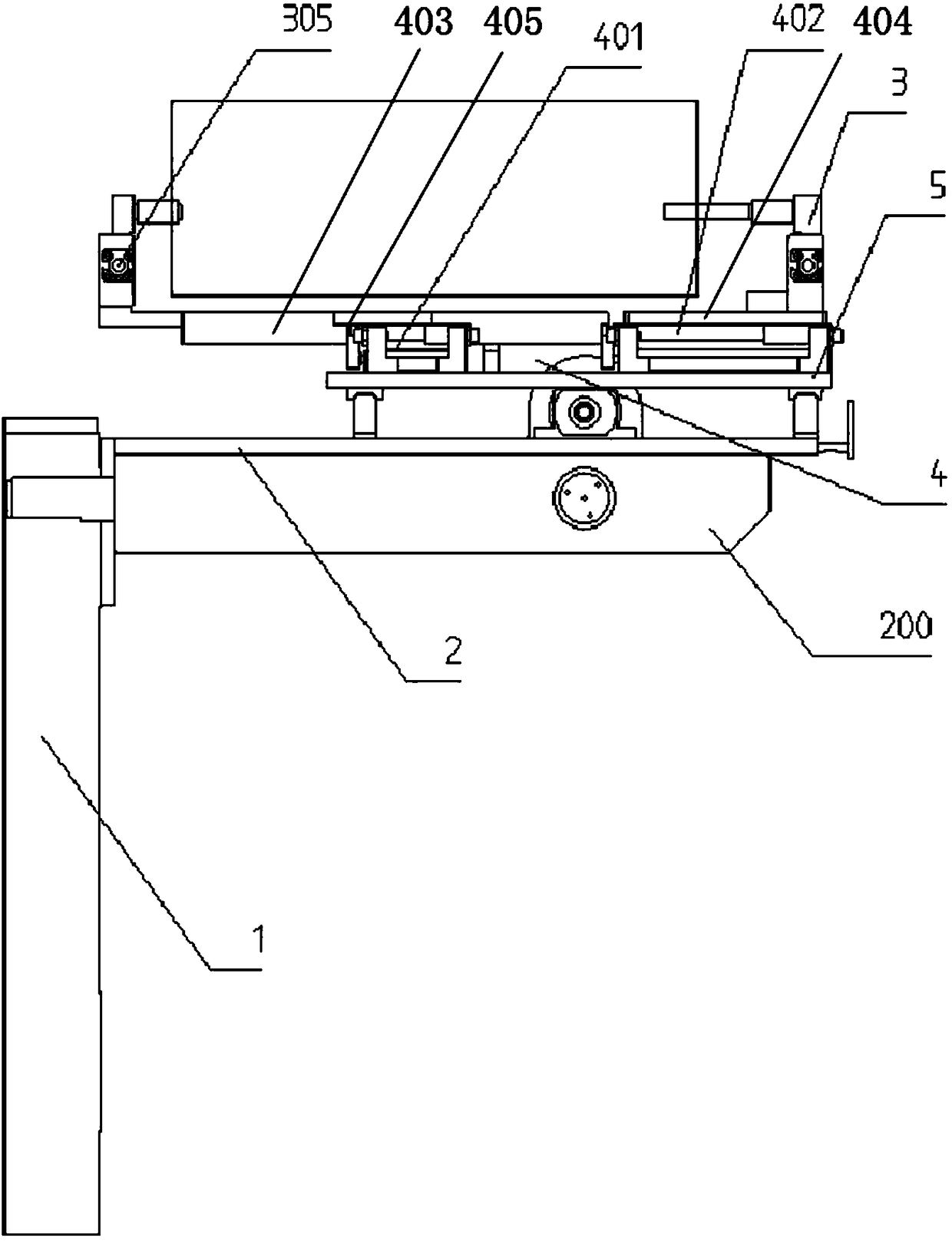
[0028] like Figure 1 to Figure 7 As shown: the cell clamping mechanism includes a lifting mechanism 1, a first base plate 2, a jaw movement mechanism unit 3, a jaw adjustment mechanism unit 4, a second base plate 5, a line rail assembly 6, a screw adjustment mechanism 7, and a motor 8. Driving gear 9, driven gear 10, ball screw 11, screw nut 12, connecting block 13, reinforcing rib 200, r...


PUM


Abstract

The invention relates to a battery clamping mechanism, which is characterized in that it includes a first bottom plate, a clamping jaw movement mechanism and a stretching movement mechanism; two second bottom plates capable of relative movement are symmetrically arranged on the first bottom plate The jaw movement mechanism includes two jaw movement mechanism units symmetrically arranged on the two second bottom plates; the jaw movement mechanism unit includes a left jaw and a right jaw for clamping the left and right ends of the electric core; The stretching motion mechanism includes a stretching drive device installed on the first bottom plate, and the power output end of the stretching drive device is connected to two second bottom plates to make the second bottom plates move relative to each other, so that the two jaw movement mechanism units will clamp The tight battery pulls flat. The invention flattens the circular battery core to obtain a flat battery core, avoids the problems of low winding efficiency of the flat battery core and uneven tension in winding the flat battery core in the prior art, and improves the quality of the battery core.

Description

technical field [0001] The invention relates to a cell clamping mechanism, in particular to a cell clamping mechanism used in a lithium battery production system, and belongs to the technical field of battery automation manufacturing equipment. Background technique [0002] Lithium-ion battery is a new generation of green high-energy battery with excellent performance, and has become one of the focuses of high-tech development. Lithium-ion batteries have the following characteristics: high voltage, high capacity, low consumption, no memory effect, no pollution, small size, small internal resistance, less self-discharge, and more cycles. Because of the above-mentioned characteristics, lithium-ion batteries have been applied to many civilian and military fields such as mobile phones, notebook computers, video cameras, and digital cameras. [0003] The shapes of power lithium batteries are mainly square and round. The cells of square batteries are flat. The traditional manufac...

Claims


Application Information

Patent Timeline
Patent Type & Authority Patents(China)
IPC IPC(8): H01M10/058H01M10/04
CPCH01M10/04H01M10/058Y02E60/10Y02P70/50
Inventor 丁华是炜
Owner CONTEMPORARY AMPEREX TECH CO
Learn More