Combustion method of the burner
一种燃烧方法、燃烧器的技术,应用在燃烧器的燃烧领域,能够解决未提供有有效合适的方法等问题,达到降低NOx的效果
- Summary
- Abstract
- Description
- Claims
- Application Information
AI Technical Summary
Problems solved by technology
Method used
Image

Examples
no. 1 Embodiment approach
[0054] Hereinafter, the combustion method using the burner according to the first embodiment of the present invention will be described in detail using the drawings. In the drawings used in the following description, in order to facilitate the understanding of features, the characteristic parts may be shown enlarged for convenience, and the dimensional ratio of each component is not necessarily the same as the actual one.
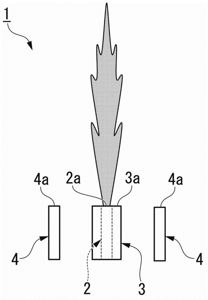
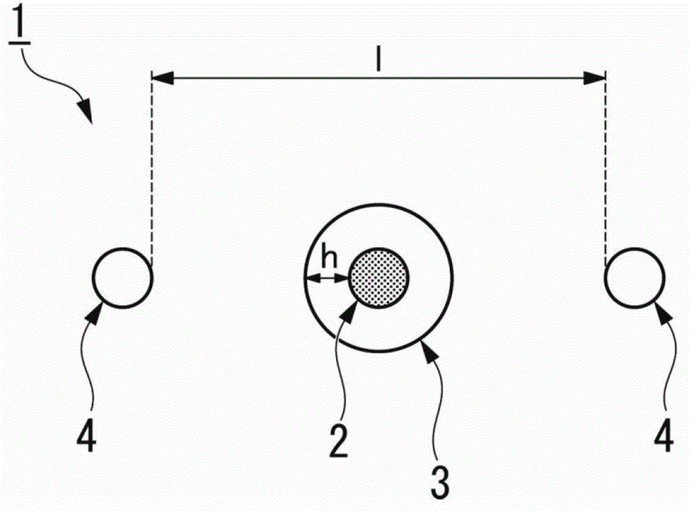
[0055] Such as figure 1 and figure 2As shown, the burner 1 used in this embodiment is roughly composed of a fuel nozzle 2 that injects a fuel flow (fuel fluid), a primary oxidant nozzle 3 that injects a primary oxidant flow (primary oxidant fluid), and a secondary oxidant flow that injects (secondary oxidant fluid) of a plurality of secondary oxidant nozzles 4 constitute.
[0056] Such as figure 1 As shown, the fuel nozzle 2, the primary oxidant nozzle 3, and the secondary oxidizer nozzle 4 are all formed in a cylindrical shape, and their longitudinal d...
no. 2 Embodiment approach
[0113] Next, a combustion method using the burner according to the second embodiment of the present invention will be described.
[0114] This embodiment is a modified example of the first embodiment, and description of the same parts will be omitted.
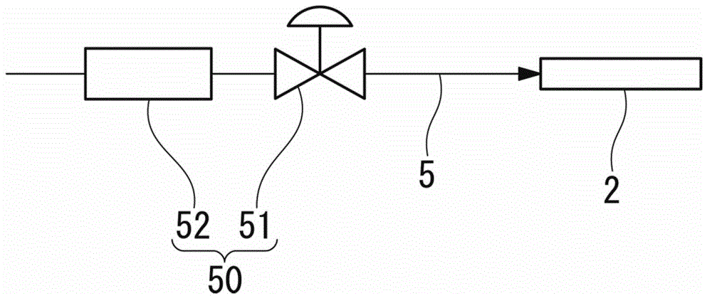
[0115] The present embodiment is different from the first embodiment in that the flow rate of the fuel flow is controlled to be changed periodically, and other burner structures are the same.
[0116] In the present embodiment, the flow rate of the fuel flow changes periodically, and the periodic change in the flow rate of the fuel flow and the periodic change in the oxygen ratio are controlled to have the same frequency.
[0117] In addition, the phase difference between the flow rate of the fuel flow and the periodic change of the oxygen ratio is controlled to be above π / 2 and below 3π / 2 (that is, the absolute value of the phase difference between the flow rate of the fuel flow and the periodic change of the oxygen ratio is π...
Embodiment 1
[0131] In embodiment 1, use burner 1 to carry out experiment, described burner 1 is in the side of the test furnace of cuboid, as figure 1 and figure 2 As shown, the primary oxidant nozzle 3 is arranged to surround the outer periphery of the fuel nozzle 2, and the two secondary oxidant nozzles 4 are arranged on the same plane at positions symmetrical to each other with the fuel nozzle 2 as the axis center. The distance l between the two secondary oxidant nozzles 4 was set to 50 cm, and the flow velocity of the secondary oxidant flow ejected from the secondary oxidant nozzles 4 was set to 100 m / s. At the bottom of the test furnace, a plurality of water-cooled tubes are arranged in a direction perpendicular to the ejection direction of the nozzle, and temperature-measuring resistance elements are inserted into the inlet and outlet of each water-cooled tube.
[0132] LNG is used as the fuel, the flow rate of the fuel flow is set constant, the time-averaged oxygen ratio is set t...
PUM
 Abstract
Description
Claims
Application Information
 - R&D
- Intellectual Property
- Life Sciences
- Materials
- Tech Scout
- Unparalleled Data Quality
- Higher Quality Content
- 60% Fewer Hallucinations
Browse by: Latest US Patents, China's latest patents, Technical Efficacy Thesaurus, Application Domain, Technology Topic, Popular Technical Reports.
© 2025 PatSnap. All rights reserved.Legal|Privacy policy|Modern Slavery Act Transparency Statement|Sitemap|About US| Contact US: help@patsnap.com