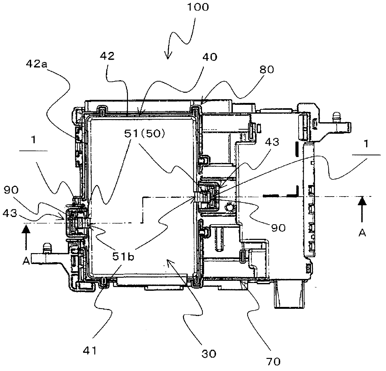
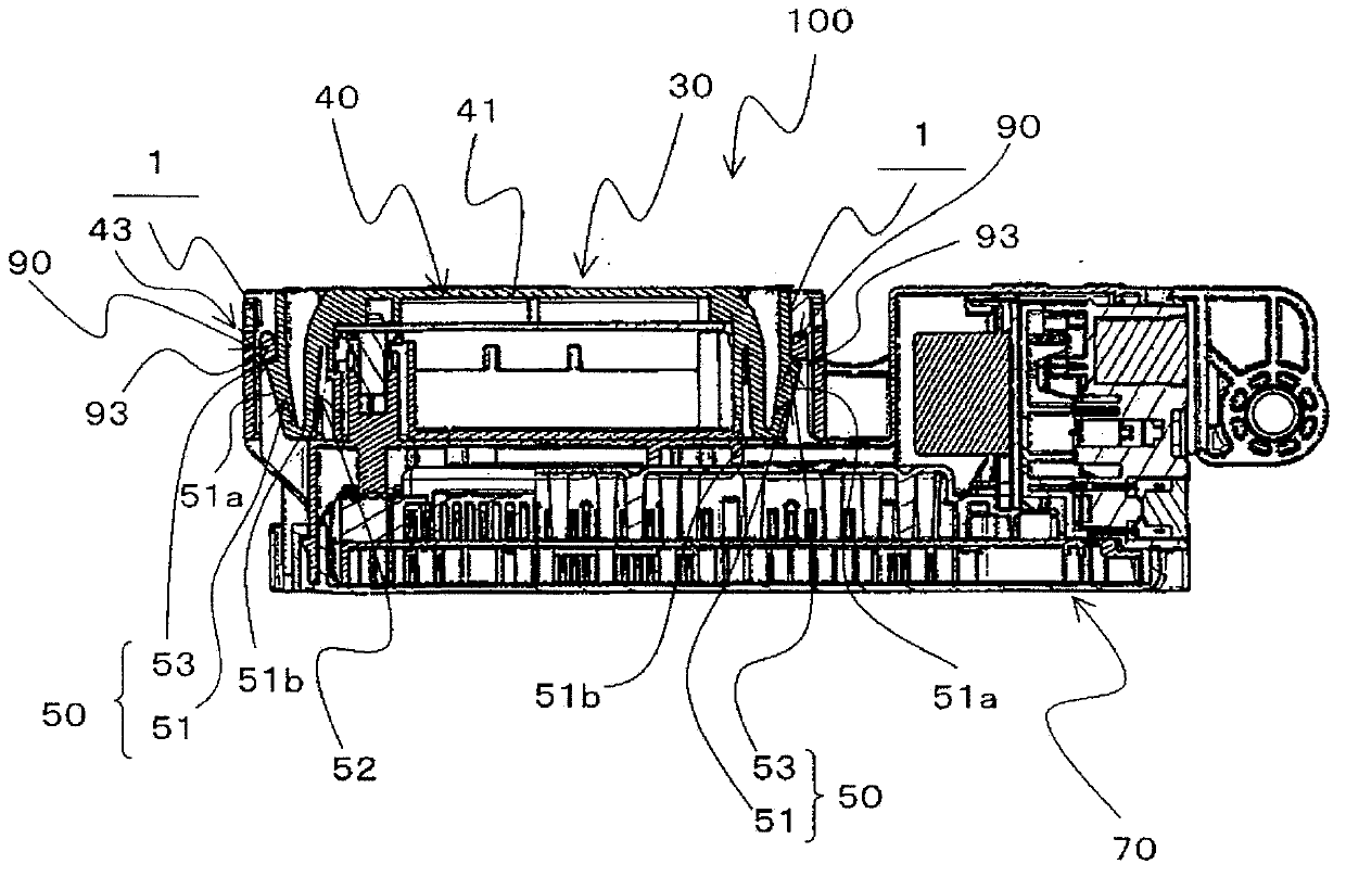
Clamping structure
A technology for engaging structures and engaging parts, applied in coupling devices, devices for engaging/disconnecting connected parts, and two-part connecting devices, etc., can solve problems such as unrealized engagement, and achieve increased engagement margin, The effect of reducing looseness
- Summary
- Abstract
- Description
- Claims
- Application Information
AI Technical Summary
Problems solved by technology
Method used
Image
Examples
Deformed example 1
[0083] Next, use Figure 7 Modification 1 of the engaging structure 1 of the embodiment of the present invention will be described. Figure 7 It is an enlarged cross-sectional view of the periphery of the engagement structure 1 according to Modification 1 of the embodiment of the present invention.
[0084] The difference between the engagement structure 2 of Modification 1 and the engagement structure 1 of the embodiment is that it has an engagement protrusion 200 instead of the engagement protrusion 53 , and has an engaged portion 300 instead of the engaged portion 93 .
[0085] In addition, other structures are the same as those in the embodiment, and the same symbols are attached to the same structure as the embodiment.
[0086] When the engaging protrusion 200 and the engaged portion 300 are engaged with each other, the opposing surfaces 210, 310 that are engaged with each other are divided into two parts from the engaging protrusion in the direction perpendicular to the...
Deformed example 2)
[0089] Next, use Figure 8 Modification 2 of the engaging structure 1 of the embodiment of the present invention will be described. Figure 8 It is an enlarged cross-sectional view of the periphery of the engagement structure 3 according to Modification 2 of the embodiment of the present invention.
[0090] The engaging structure 3 of the modification 2 differs from the engaging structure 1 of the embodiment in that it has an engaging protrusion 400 instead of the engaging protrusion 53 , and has an engaged portion 500 instead of the engaged portion 93 .
[0091] In addition, other structures are the same as those in the embodiment, and the same symbols are attached to the same structure as the embodiment.
[0092] In the engaging protruding portion 400 and the engaged portion 500, each step surface 410, 510 forming a step difference between the two step surfaces 54a, 54b, 94a, 94b is from the lower step surface 54a, 94a toward the upper step surface. The stepped surfaces 54...
Deformed example 3)
[0095] Next, use Figure 9 Modification 3 of the engagement structure 1 of the embodiment of the present invention will be described. Figure 9 It is an enlarged cross-sectional view of the periphery of the engagement structure 4 according to Modification 3 of the embodiment of the present invention.
[0096] The difference between the engagement structure 4 of the modification 3 and the engagement structure 1 of the embodiment is that it has an engagement protrusion 600 instead of the engagement protrusion 53 , and has an engaged portion 700 instead of the engaged portion 93 .
[0097] In addition, other structures are the same as those in the embodiment, and the same symbols are attached to the same structure as the embodiment.
[0098] Of the engaging protrusion 600 and the engaged portion 700 , the swing front end 610 and the relative movement front end 710 are each formed in a tapering shape with a rounded tip.
[0099] The engaging structure 4 of the modified example 3...
PUM
 Abstract
Description
Claims
Application Information
 - R&D
- Intellectual Property
- Life Sciences
- Materials
- Tech Scout
- Unparalleled Data Quality
- Higher Quality Content
- 60% Fewer Hallucinations
Browse by: Latest US Patents, China's latest patents, Technical Efficacy Thesaurus, Application Domain, Technology Topic, Popular Technical Reports.
© 2025 PatSnap. All rights reserved.Legal|Privacy policy|Modern Slavery Act Transparency Statement|Sitemap|About US| Contact US: help@patsnap.com


