Eureka AIR delivers breakthrough ideas for toughest innovation challenges, trusted by R&D personnel around the world.

Mixed tower supporting structure capable of being used in large-size land wind generating set

A technology for wind turbines and support structures, which is applied to wind turbine components, wind engines, and wind power generation. It can solve problems such as increase in size, difficulty in transportation and manufacturing, and increase in cost, and achieve the effect of improving economic efficiency.

Inactive Publication Date: 2013-12-04
SHANGHAI ELECTRIC WIND ENERGY CO LTD
View PDF6 Cites 2 Cited by
  • Summary
  • Abstract
  • Description
  • Claims
  • Application Information

AI Technical Summary

Problems solved by technology

[0004] The general road height limit is 4.5 meters. At present, the diameter of the tower of the wind power generation unit is generally 4.2 meters, but the bottom diameter of the 5MW unit on the market has reached 6 meters, which causes great difficulties in transportation and manufacturing. big increase
And with the further increase of the unit capacity of the wind turbine and the diameter of the wind rotor, the load on the tower increases sharply, and the tower becomes higher and higher. For places where the wind shear is relatively large, the development of wind resources also develops to a higher level. The center of the hub The height is getting higher and higher, and the diameter of the tower is getting bigger and bigger, especially the diameter of the lower part of the tower. However, due to the limitation of the bolt connection and the transportation road, the diameter of the tower cannot be increased without limit, so the steel conical tower It has unsolvable limitations when solving the support structure of taller and larger capacity wind turbines

Method used


Image

  • Mixed tower supporting structure capable of being used in large-size land wind generating set

Examples


Embodiment Construction

[0010] The present invention will be further described below in conjunction with accompanying drawing.

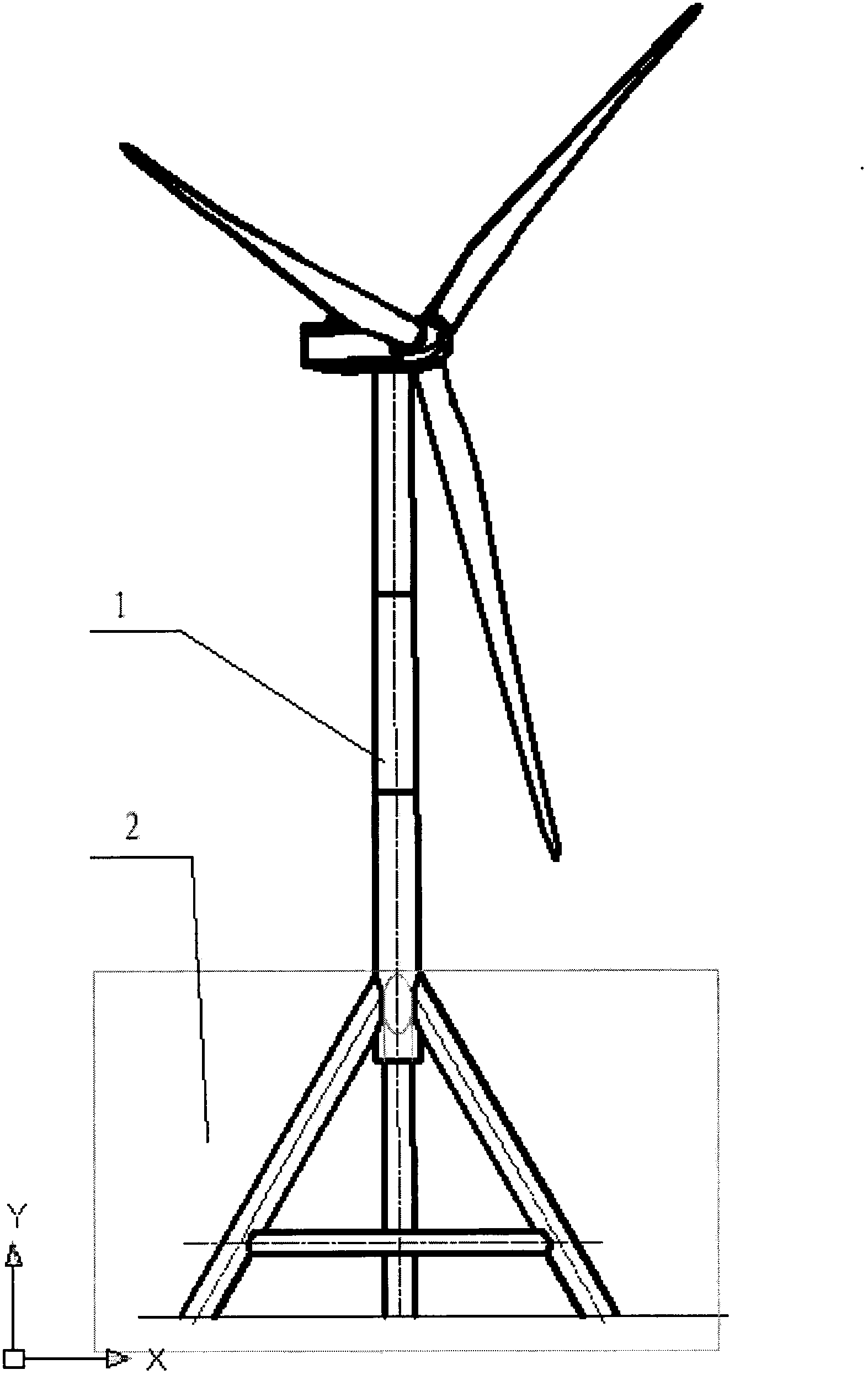
[0011] The picture is a schematic diagram of a hybrid tower support structure that can be used for large-scale onshore wind turbines. It can be seen from the figure that the hybrid tower is divided into two parts, and the upper part adopts a traditional conical steel cylinder tower (1) , the lower part adopts other supporting structures (2), and the two parts are connected together to form the supporting structure of the wind power generating set.

[0012] The other supportable structure (2) may be a jacket structure, a concrete structure, or a truss structure.

[0013] A hybrid tower support structure that can be used for large-scale land-based wind power generators according to the present invention can meet the tower design of wind power generators with different capacities and arbitrary heights through the combination of the two structures. For large-capacity wind power...


PUM


Abstract

The invention relates to a supporting structure of a wind generating set, in particular to a mixed tower supporting structure capable of being used in a large-size land wind generating set. In the prior art, a supporting structure of the land wind generating set is mainly of a conical cylinder-type tower made of steel, the tower is transported to a wind field after being manufactured in a segmented mode, and then the tower is connected and installed to a foundation ring embedded into a foundation. The height of an ordinary road is limited to 4.5m, however, the diameter of the bottom of a 5MW set in the market has reached 6m; with the development of the wind power industry, the center height of a hub and the diameter of the tower become larger and larger, and especially, the diameter of the lower portion of the tower causes great difficulty to transportation and manufacturing of the tower. The mixed tower supporting structure is divided into two parts, the upper portion is the traditional conical cylinder-type tower made of the steel, the lower portion is other supporting structures, solutions are provided for design and installation of large-capacity wind generating sets and ultrahigh towers, and meanwhile, the economy of the supporting structure of the wind generating set is improved to some extent.

Description

Technical field: [0001] The invention relates to a support structure of a wind power generating set. Background technique: [0002] The support structure of the wind turbine mainly bears the gravity load of the wind turbine and the aerodynamic load transmitted from the wind rotor. [0003] The support structure of existing onshore wind turbines is mainly composed of steel conical towers and foundation rings embedded in the foundation. The foundation ring and foundation are poured at the installation site. Constraints, usually divided into several sections, are manufactured by the tower factory and transported to the installation site of the wind turbine, where they are connected and installed by bolts. [0004] The general road height limit is 4.5 meters. At present, the diameter of the tower of the wind power generation unit is generally 4.2 meters, but the bottom diameter of the 5MW unit on the market has reached 6 meters, which causes great difficulties in transportation...

Claims


Application Information

Patent Timeline
IPC IPC(8): F03D11/00
CPCY02E10/722Y02P70/50
Inventor 陈晓静李贺
Owner SHANGHAI ELECTRIC WIND ENERGY CO LTD
Why Eureka
Eureka Blog
Learn More