Material pushing device of stainless steel solid melting furnace

A pusher, stainless steel technology, applied in furnaces, furnace components, furnace types, etc., can solve the problems of high labor intensity and high frequency of bundling, and achieve the effects of convenient operation, improved work efficiency, and reduced production costs.

Inactive Publication Date: 2013-12-04
兴化市华恺不锈钢异型材厂
View PDF0 Cites 4 Cited by
  • Summary
  • Abstract
  • Description
  • Claims
  • Application Information

AI Technical Summary

Problems solved by technology

[0004] The invention provides a material pushing device for a stainless steel solid melting furnace, which solves the problems of high binding frequency and high labor intensity, can quickly and conveniently bundle and transport stainless steel pipes, reduces the labor intensity of workers, and improves work efficiency

Method used


Image

  • Material pushing device of stainless steel solid melting furnace
  • Material pushing device of stainless steel solid melting furnace
  • Material pushing device of stainless steel solid melting furnace

Examples


Embodiment Construction

[0014] Below in conjunction with accompanying drawing, the present invention will be described in further detail:

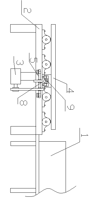
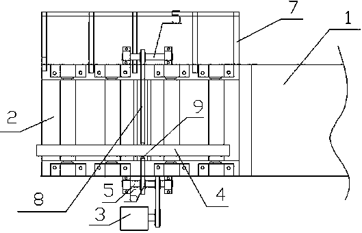
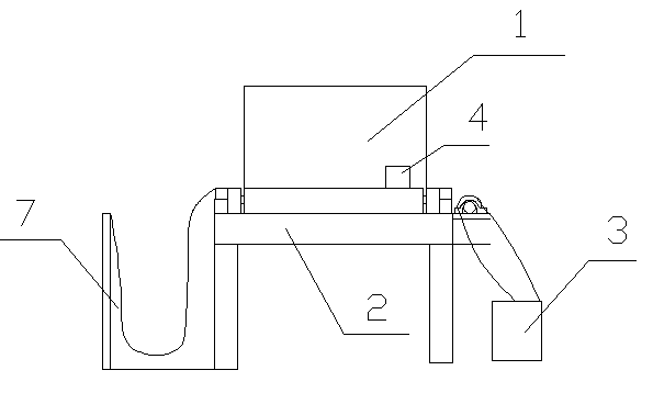
[0015] Such as figure 1 , 2 Shown in , 3: a kind of pushing device of stainless steel solid melting furnace of the present embodiment, comprises solid melting furnace 1 and the discharge conveyer frame 2 that is positioned at one end of the outlet of described solid melt furnace 1, and described discharge conveyer frame 2 is fixedly arranged There is a pushing device.

[0016] The pushing device includes a motor 3, a push rod 4, a gear 6, a chain 8, a cover rod 9, and a collecting frame 7; track wheels and a cover rod 9 are installed at the bottom of the push rod 4, and the cover rod 9 is located at two between the track wheels; the track wheels are respectively slid and fixed on the two parallel tracks set on the discharge conveyor frame 2, and the two ends of the tracks are respectively provided with bearings with seat belts to rotate and fix on the discharge...


PUM


Abstract

The invention discloses a material pushing device of a stainless steel solid melting furnace, which comprises a solid melting furnace and a discharged-material conveying frame positioned at one end of a discharge port of the solid melting furnace, wherein the discharged-material conveying frame is fixedly provided with a material pushing device; the bottom of a push rod is provided with track wheels and a sleeve rod; the sleeve rod is disposed between the two track wheels; the track wheels are respectively fixedly disposed on two parallel tracks respectively disposed on the discharged-material conveying frame in a sliding way; the two ends of the tracks are respectively provided with cross shafts fixedly disposed at side edges of the discharged-material conveying frame by mounted bearings in a rotating way; each cross shaft is fixedly connected with a gear; one end of one of the cross shafts is also fixedly provided with a transmission gear; the transmission gear is connected with a motor; the two gears are connected with each other by a chain; and two ends of the chains are respectively fixedly connected with two ends of the sleeve rod. The material pushing device of the stainless steel solid melting furnace, disclosed by the invention, has the advantages of reasonable design and convenience in operation; the stainless steel pipes can be rapidly and conveniently bundled and conveyed; and moreover, the production cost is reduced and the working efficiency is increased.

Description

technical field [0001] The invention relates to a material pushing device for a stainless steel solid melting furnace. Background technique [0002] When making stainless steel pipes, due to the different temperature and cooling speed of each section of cold rolling, the structure of the stainless steel pipes is inconsistent, the crystal lattice is defective, and the corrosion resistance of the stainless steel pipes is reduced. This requires the use of a stainless steel pipe solid melting furnace for solid solution softening , so that the composition of the stainless steel pipe is consistent, eliminating hardening, in order to facilitate the continued cold working, and restore the corrosion resistance of stainless steel to the best state. [0003] The stainless steel pipe comes out of the stainless steel melting furnace and is sent to the discharge conveyor frame, and the stainless steel pipe is transported out by a crane. However, although the stainless steel pipe is...

Claims


Application Information

Patent Timeline
Patent Type & Authority Applications(China)
IPC IPC(8): C21D1/00C21D9/08F27D3/04
Inventor 徐国华
Owner 兴化市华恺不锈钢异型材厂
Why Eureka
Try Eureka