Main rope wedge ejector and main rope wedge ejector system

A wedge and wedge-shaped technology, applied in hoisting devices, spring mechanisms, etc., can solve problems such as corrosion, unfavorable safety construction, and inability to withdraw peach-shaped rings, etc., to ensure construction safety, meet safe construction, and improve production efficiency effect

Active Publication Date: 2016-03-23
HUAINAN MINING IND GRP
View PDF7 Cites 0 Cited by
  • Summary
  • Abstract
  • Description
  • Claims
  • Application Information

AI Technical Summary

Problems solved by technology

Every time the rope is escaped, the hammering part 101 is manually smashed down with a sledgehammer bit by bit, and the peach-shaped ring 104 is withdrawn through the penetrating rod 102. This method is extremely unfavorable for safe construction due to the long working time. In the process, it takes about 1 hour to remove the peach-shaped ring in a wedge-shaped device each time
[0004] figure 2 It is a schematic diagram of exiting the peach-shaped ring by pressing down the bolt in the prior art, and the manufacturer of the wedge connection device also provides a method for removing the peach-shaped ring by screwing the bolt, such as figure 2 As shown, it includes the bolt 201 and the dovetail groove fixing block 202 of the wedge remover. However, due to the influence of environmental conditions, the main suspension wedge connection device will be corroded after being used for a period of time. too small to withdraw from the peach ring
Both of the above two methods require personnel to work in front of the device, and the operation time is long. If the penetrating rod breaks or is damaged, it is very likely to cause casualties, which is extremely unfavorable for safe construction

Method used


Image

  • Main rope wedge ejector and main rope wedge ejector system
  • Main rope wedge ejector and main rope wedge ejector system
  • Main rope wedge ejector and main rope wedge ejector system

Examples


Embodiment Construction

[0039] In order to make the purpose, technical solutions and advantages of the embodiments of the present invention clearer, the technical solutions in the embodiments of the present invention will be clearly and completely described below in conjunction with the drawings in the embodiments of the present invention. Obviously, the described embodiments It is a part of embodiments of the present invention, but not all embodiments. Based on the embodiments of the present invention, all other embodiments obtained by persons of ordinary skill in the art without creative efforts fall within the protection scope of the present invention.

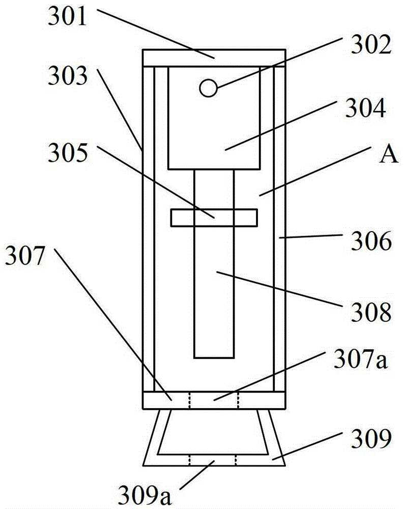
[0040] image 3 It is the structural representation of the main rope wedge ejector of the present invention, as image 3 As shown, the main rope wedge extractor includes an outer frame, wherein the outer frame includes a top plate 301, side plates (303, 306) and a bottom plate 307, and the top plate 301, side plates (303, 306) and bottom plate 30...


PUM


Abstract

The invention discloses a main rope wedge withdrawing device and a main rope wedge withdrawing device system. The main rope wedge withdrawing device comprises an outer framework, the outer framework comprises a top plate, side plates and a base plate, a containing space is arranged in the outer framework, a first through hole is formed in the base plate, a dovetail groove fixing block is fixedly arranged below the base plate, and a second through hole coaxial with the first through hole is formed in the bottom surface of the dovetail groove fixing block; an oil cylinder is arranged below the top plate in the containing space, a through rod is perpendicularly connected to the lower end of the oil cylinder, and the through rod, driven by the oil cylinder, penetrates through the first through hole and the second through hole in sequence. By means of the main rope wedge withdrawing device and the main rope wedge withdrawing device system, the safe reliability of a winch main rope in the processes of rope threading, rope cutting and rope replacement is improved, unsafe factors caused by fatigue feelings of staff due to high-intensity and long term work are avoided, and safety construction requirements are met.

Description

technical field [0001] The invention relates to a wedge ejector device in a mine hoisting winch system, in particular to a main rope wedge ejector and a main rope wedge ejector system. Background technique [0002] Mine winch hoisting system, especially vertical shaft winch hoisting, the main rope is mostly a wedge connection device. Due to the harsh environment of the mine, coupled with water spraying, etc., after a period of use, the main rope and the connecting device will rust together, especially after the rust has been rusted for several months, the corrosion is more serious. Or when changing rope, all will spend a large amount of time in this link, have a strong impact on construction progress, more unfavorable safe operation. Especially for the friction wheel hoist, after the main rope has been working for a period of time, its natural elongation will affect the normal safety production, and almost every set of main ropes will have to run about 5 times during use. ...

Claims


Application Information

Patent Timeline
Patent Type & Authority Patents(China)
IPC IPC(8): B66D1/28B66D1/54
Inventor 张孝山朱少军王兴胜
Owner HUAINAN MINING IND GRP
Why Eureka
Try Eureka