
Outer Fuel Tank Access Covers, Wings and Vehicles

A technology for a fuel tank and an access cover, applied in the field of aircraft, can solve the problem of a pressure vessel without a release valve, etc., and achieve the effects of light weight, reduced rigidity requirements, and reduced rigidity

Active Publication Date: 2016-11-23
AIRBUS OPERATIONS GMBH
View PDF6 Cites 0 Cited by
  • Summary
  • Abstract
  • Description
  • Claims
  • Application Information

AI Technical Summary

Problems solved by technology

In fact, currently, pressure vessels without relief valves are produced

Method used


Image

  • Outer Fuel Tank Access Covers, Wings and Vehicles
  • Outer Fuel Tank Access Covers, Wings and Vehicles
  • Outer Fuel Tank Access Covers, Wings and Vehicles

Examples


Embodiment Construction

[0029] After outlining the objects of the present invention, specific non-limiting embodiments will be described below.

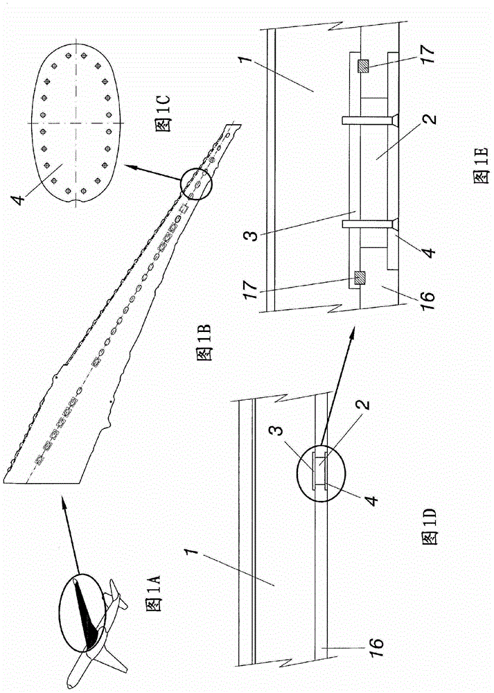
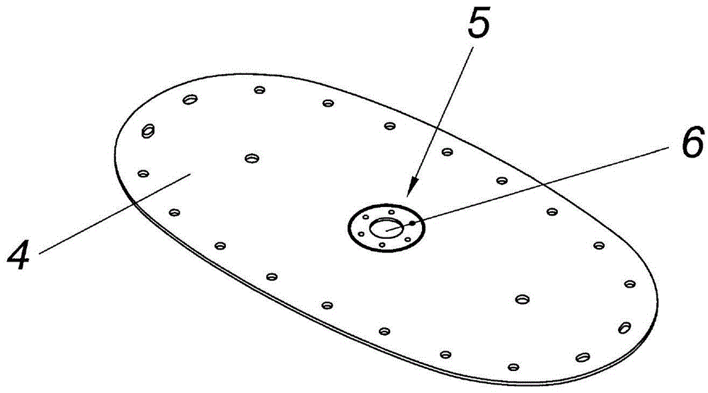
[0030] All embodiments of the invention are located in the external FTAC 4 . exist Figure 1A An embodiment of the aircraft is shown in and in Figure 1B The left wing of the aircraft is shown in , where Figure 1B FTAC is shown in ( Figure 1C ) at the location. exist Figure 1D A cross-sectional view of the inner area of ​​the wing in which the fuel tank 1 is positioned is shown in . In addition, in Figure 1D and 1E The relative position of the FTAC with respect to the fuel tank 1 is shown in . The inner FTAC 3 is located in the fuel tank 1 and is sealed to the lower wing skin 16 by a fuel seal 17 . The outer FTAC 4 is secured to the lower wing skin 16 by a plurality of mounting holes distributed along the periphery. In one embodiment of the invention the fixing means are bolts. Various embodiments of the invention are located in the outer FTAC...


PUM


Abstract

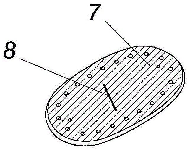
The present invention describes an outer fuel tank access cover (4) (FTAC) of an aircraft comprising an explosion gas relief means (8) adapted for letting the explosion gases escape to the atmosphere, a wing comprising such outer FTAC (4) of an aircraft and an aircraft. The invention belongs to the field of designing auxiliary pieces in the wing of aircraft to control the risk of gases from an explosion occurred in the FTAC entering the fuel tank.

Description

technical field [0001] The present invention describes an outer fuel access tank cover (FTAC) of an aircraft, a wing including the further FTAC of the aircraft, and the aircraft. The invention belongs to the field "Design of auxiliary components in the wing of an aircraft to control the risk of gas entering the fuel tank from a deflagration occurring in an FTAC". Background technique [0002] Manholes in the aircraft provide access to the fuel tanks. The manhole includes an inner fuel tank access cover (inner FTAC), an outer FTAC, and a void area between the two covers. A fuel tank access cover (FTAC) is mechanically fastened and clamped to the aircraft wing skin to provide a fuel tank access seal. FTACs are designed to meet a wide range of requirements, some of which are: no fuel leaks, fire protection, resistance to crashes caused by UERF (Uncontained Engine Rotor Failure Fault), EMH / lightning strike, seal friction, and airfoil bending. In addition to the "no fuel leak...

Claims


Application Information

Patent Timeline
Patent Type & Authority Patents(China)
IPC IPC(8): B64C3/34
CPCB64C3/34B64D37/005B64D37/32Y02T50/40B64C1/14B64C1/1446
Inventor 马科斯·阿拉斯拉基
Owner AIRBUS OPERATIONS GMBH
Learn More