Waste plastic thin film friction washing machine

A technology of friction cleaning machine and plastic film, which is applied in cleaning methods and utensils, cleaning methods using liquids, chemical instruments and methods, etc., which can solve leak hole rupture, huge repair and maintenance costs, poor drainage of the cleaning machine casing, etc. problem, to achieve the effect of smooth friction and shifting blades, long friction and cleaning time, and ideal cleaning effect

Active Publication Date: 2013-12-04
ZHANGJIAGANG LIANDA MACHINERY
View PDF7 Cites 20 Cited by
  • Summary
  • Abstract
  • Description
  • Claims
  • Application Information

AI Technical Summary

Problems solved by technology

However, the current structure has the following defects: 1. The leakage hole is arranged on the casing, and the main shaft is rotated and installed on the casing. The area of ​​the leakage hole should not be too large. The requirement of rotating support also reduces the service life of the machine. Therefore, the leakage area of ​​the current cleaning machine is small, which causes poor drainage in the casing of the cleaning machine. The humidity of the discharged material is high, and there will be certain sewage, which will affect Subsequent rinsing work; 2. Since the screw blade is set on the main shaft, the material is driven by the main shaft in the casing and moves to the discharge port, and the friction time of the material in the casing is determined by the speed at which the main shaft pushes the material. The friction time of the cleaning machine material in the casing is short, and the cleaning effect is not enough
3. Due to the friction of the material in the casing, especially the part of the leak hole is more likely to be worn, and once the leak hole wears too much, it is very likely to cause the leak hole to rupture, so that the material may leak from the leak hole, affecting normal use. If the leak hole is broken, only the casing can be replaced, resulting in huge repair and maintenance costs

Method used


Image

  • Waste plastic thin film friction washing machine
  • Waste plastic thin film friction washing machine
  • Waste plastic thin film friction washing machine

Examples


Embodiment Construction

[0021] The present invention will be described in further detail below through specific examples.

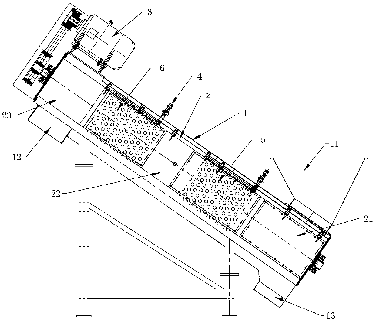
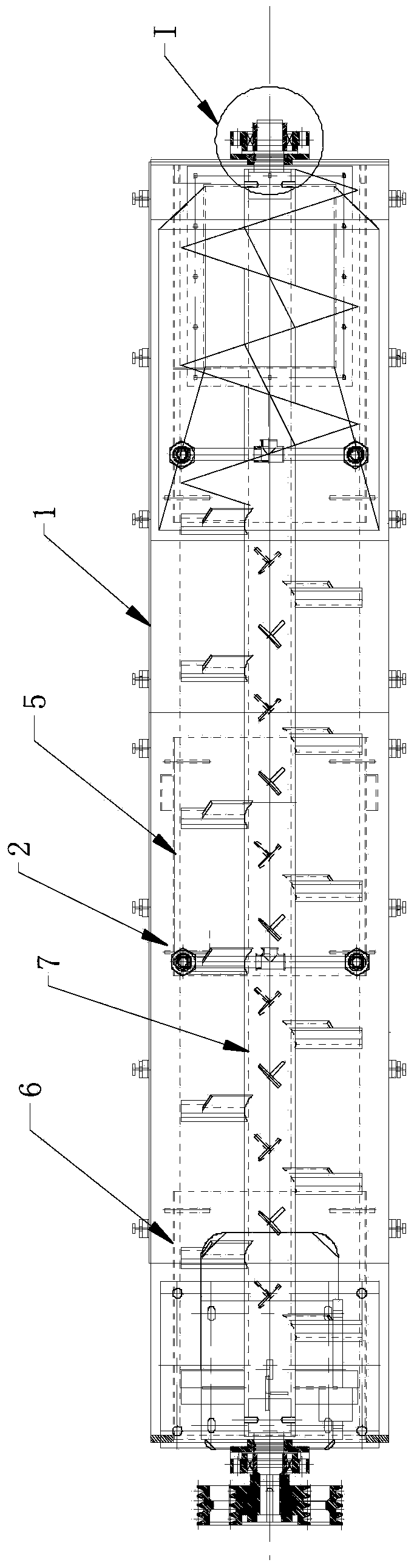
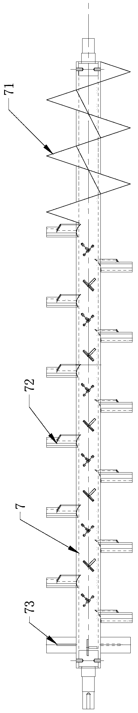
[0022] Such as figure 1 , 2 , 4, a waste plastic film friction cleaning machine, including a casing 1, the arrangement of the casing 1 can be horizontal arrangement, also can be inclined, the arrangement is according to the position of the front and rear equipment of the friction cleaning machine, so that For its connection, the casing 1 is arranged obliquely, and the inner cylinder 2 described later is also arranged obliquely like the casing 1 , and the feed inlet 11 is arranged at the lower end of the casing 1 . One end of the casing 1 is provided with a material inlet 11, the other end is provided with a material outlet 12, the bottom is provided with a sewage outlet 13, the material inlet 11 is arranged on the top of the casing 1, and the material outlet 12 and the sewage outlet 13 are located The bottom of the shell 1, wherein the shell 1 includes a frame, an upper top co...


PUM


Abstract

The invention discloses a waste plastic thin film friction washing machine, which comprises an enclosure, an inner barrel and a main shaft, wherein the inner barrel is axially and fixedly arranged in the enclosure, and comprises a charging friction section, a discharging section and a middle friction section; a first tubular screen is arranged between the charging friction section and the middle friction section, and a second tubular screen is arranged between the discharging section and the middle friction section; the main shaft is arranged in the enclosure in a rotating way, and is driven by a main shaft power device to rotate; a helical pushing blade is arranged within the range of the charging friction section on the main shaft, a plurality of discharging blades are arranged within the range of the discharging section on the main shaft, and friction stirring blades are arranged within a range between the charging friction section and the discharging section on the main shaft; flushing water pipes for flushing the first and second screens and a water supply pipe orifice for supplying water to the inner barrel are arranged on the enclosure. According to the washing machine, the strength of the enclosure of the washing machine can be ensured, and meanwhile, the areas of the screens can be enlarged, so that the sewage discharge efficiency of the washing machine is improved, and a material can be washed long enough in the inner barrel in a friction way.

Description

technical field [0001] The invention relates to the field of film technology, in particular to a waste plastic film friction cleaning machine. Background technique [0002] The current friction cleaning machine generally includes a casing. One end of the casing is provided with a feed port, the other end is provided with a discharge port, and the bottom is provided with a sewage outlet; A leakage hole is arranged on the casing, and a water supply pipe for supplying water to the inside of the casing is arranged on the casing. The material enters from the feed port and is driven by the main shaft to rotate, friction between materials, friction between materials and blades, friction between materials and the inner wall of the casing, and at the same time, the water supply pipe supplies water to the casing, so that the waste plastic film can be rubbed and cleaned. , while the sewage flows out from the leakage hole, and finally the material is exported through the discharge port...

Claims


Application Information

Patent Timeline
IPC IPC(8): B08B3/10B08B13/00
Inventor 潘学明郑勇
Owner ZHANGJIAGANG LIANDA MACHINERY
Why Eureka
Try Eureka