
A High Precision Current Sampling Circuit for Smart Meter

A current sampling and smart meter technology, applied in the directions of indicating the existence of current/voltage, changing the range circuit, measuring electrical variables, etc., can solve the problems of reducing the sampling accuracy, limited current acquisition channels of the metering unit, and complex implementation methods.

Active Publication Date: 2015-09-23
YANGZHOU WANTAI ELECTRIC TECH CO LTD
View PDF6 Cites 1 Cited by
  • Summary
  • Abstract
  • Description
  • Claims
  • Application Information

AI Technical Summary

Problems solved by technology

In the prior art, the shunt current sampling circuit such as Image 6 As shown, the transformer current sampling circuit in the prior art is as Figure 7 As shown, due to the restriction of the dynamic range of the metering chip, it cannot guarantee high-precision measurement in the entire current range, and cannot meet the requirements of precise measurement of ultra-large current and extremely small current at the same time.
In response to this problem, Chinese patent CN102809678 A and Chinese patent CN102426290 A have proposed improved design methods, but the implementation methods are relatively complicated and unrealistic in actual use. The main reasons are as follows: (1) Due to the The type specifications of various electric energy meters have been formulated, and the external dimensions and shapes of electric energy meters cannot be changed, so it is impossible to allow too many circuits to be added. This problem exists in the above-mentioned patents; (2) Since the State Grid Corporation implements unified bidding and procurement of electric energy meters , through four years of bidding and procurement, the purchase price of electric energy meters has basically stabilized. An increase in the cost of a few yuan will result in the failure to win the bid because the bid price is too high or the bid price is appropriate so that there will be no profit after winning the bid. Therefore, it is impossible to allow too much increase Multi-circuits, the above patents also have this problem; (3) adding too many circuits before the voltage sampling and current sampling circuits may not only reduce the sampling accuracy, but may also cause electromagnetic compatibility problems, the above patents also This problem exists in all; (4) Due to the limited current acquisition channel of the metering unit of the MCU in the metering chip or SOC scheme, it is not allowed to collect the current in segments by size through different acquisition terminals to improve the acquisition accuracy. Chinese patent CN102426290 A there is this problem

Method used


Image

  • A High Precision Current Sampling Circuit for Smart Meter
  • A High Precision Current Sampling Circuit for Smart Meter
  • A High Precision Current Sampling Circuit for Smart Meter

Examples


Embodiment Construction

[0027] specific implementation plan

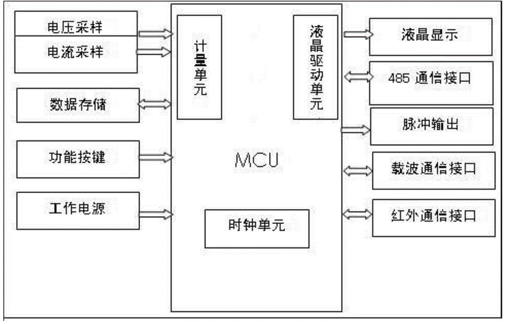
[0028] The present invention as Figure 1-4 As shown, the smart meter includes an MCU (the main chip MCU adopts V9811), and the MCU is equipped with a differential amplifier group, and the differential amplifier group includes a differential amplifier 1 for collecting live wire current and a differential amplifier 2 for collecting neutral wire current; and The first differential amplifier and the second differential amplifier are respectively connected with wide metering current sampling circuits.

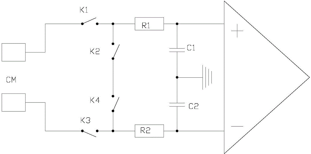
[0029] The wide metering current sampling circuit is a shunt current sampling circuit, and the shunt current sampling circuit includes a shunt CM, a resistor R1, a resistor R2, a capacitor C1, a capacitor C2, an analog switch K1, an analog switch K2, an analog switch K3 and Analog switch K4;

[0030] The shunt CM has a shunt interface 1 and a shunt interface 2, the rear of the shunt interface 1 is connected to the inlet of the analog switch K...


PUM


Abstract

The invention discloses a high-precision current sampling circuit of an intelligent electric meter and provides a high-precision current sampling circuit with simple circuit structure, convenience in encapsulation and low production cost. The intelligent electric meter comprises an MCU (micro control unit), wherein a differential amplifier group is arranged in the MCU and comprises a differential amplifier I for acquiring the current of a live wire and a differential amplifier II for acquiring the current of a neutral wire; the differential amplifier I and the differential amplifier II are respectively connected with a width measurement current sampling circuit. According to the high-precision current sampling circuit, a new segmental acquisition technical scheme is formed by the smart utilization of the turn-on resistance characteristic of an analog switch chip; the circuit structure is simple; a printed circuit board is not required to be greatly changed; therefore the area size of the printed circuit board is reduced as much as possible, and the problem of electromagnetic compability caused by the increase of circuits is solved to the maximum extent. The high-precision current sampling circuit is novel, unique, easy to operate and lower in cost.

Description

technical field [0001] The invention relates to the field of electric energy metering of electric energy meters, in particular to the improvement of the measuring current sampling circuit of smart electric meters used in households, offices and industries. Background technique [0002] As a metering product for electric energy metering and electricity bill settlement, smart energy meters are required to have stable and accurate metering performance, so as to ensure that the interests of both electricity consumers and power suppliers are not damaged. At present, the requirements for the current range of electric energy meters are constantly increasing, and the commonly used solution is to use a wide-range metering chip or an SOC (System on Chip) solution. In the prior art, the shunt current sampling circuit such as Image 6 As shown, the transformer current sampling circuit in the prior art is as Figure 7 As shown, due to the restriction of the dynamic range of the metering...

Claims


Application Information

Patent Timeline
Patent Type & Authority Patents(China)
IPC IPC(8): G01R15/08G01R19/15G01R11/00
Inventor 潘建华朱世林李香郎干勇徐振伟吴静王应娆
Owner YANGZHOU WANTAI ELECTRIC TECH CO LTD
Learn More