Blackbody components, energy-saving kiln and energy conservation method

A technology for black body components and energy-saving furnaces, which is applied in the field of furnaces and kilns, can solve the problems of inability to guarantee black body components 11, low installation efficiency, poor energy-saving effect, etc., and achieves the effect of solving poor energy-saving effect, quick installation, and improving energy-saving effect.

Inactive Publication Date: 2013-11-27
成都西华工业炉节能技术有限公司
View PDF6 Cites 4 Cited by
  • Summary
  • Abstract
  • Description
  • Claims
  • Application Information

AI Technical Summary

Problems solved by technology

[0004] 1. Each blackbody element can be regarded as an enhanced radiation source radiating outward from the opening side. The strongest radiation power direction of the traditional blackbody radiation source coincides with the blackbody axis, so the above installation method cannot guarantee the strongest radiation power of the blackbody element 11 The directions are all facing the heating workpiece 31, resulting in poor energy saving effect
[0005] 2. Each blackbody component is installed separately, which requires a large amount of work and low installation efficiency

Method used


Image

  • Blackbody components, energy-saving kiln and energy conservation method
  • Blackbody components, energy-saving kiln and energy conservation method
  • Blackbody components, energy-saving kiln and energy conservation method

Examples


Embodiment 1

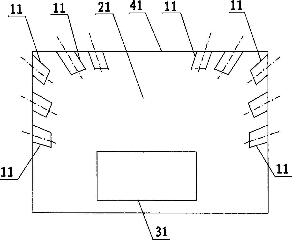
[0036] figure 2 Provided schematically the structural diagram of the energy-saving kiln of the embodiment of the present invention, as figure 2 As shown, the energy-saving kiln includes:

[0037] The furnace wall 41 encloses the furnace 21, and the structure and material of the furnace wall 41 are prior art in the field, and will not be repeated here. The heating workpiece 31 is located in the furnace 21 and occupies part of the space. The furnace wall 41 has a horizontal plane and a vertical plane;

[0038] Black body element 11, the interior of the black body element 11 is hollow, one end pointing to the center of the furnace is an opening, the other end is closed, the closed end (ie, the installation end) is installed on the furnace wall 41, the axis of the black body element or the end face of the open end Keep an inclination with the installation surface of the installation end;

[0039] image 3 Schematically gives a sectional diagram of the installation of blackb...

Embodiment 2

[0046] Figure 5 Provided schematically the structural diagram of the energy-saving kiln of the embodiment of the present invention, as Figure 5 As shown, the energy-saving kiln includes:

[0047] The furnace wall 41 encloses the furnace 21, and the structure and material of the furnace wall 41 are prior art in the field, and will not be repeated here. The heating workpiece 31 is located in the furnace 21 and occupies part of the space. The furnace wall 41 has a horizontal plane and a vertical plane;

[0048] Black body element 11 , the interior of the black body element 11 is hollow, one end pointing to the center of the furnace 21 is open, and the other end is closed, and the closed end is installed on the furnace wall 41 .

[0049] Figure 6 Schematically provides a schematic cross-sectional diagram of the installation of the black body element of the embodiment of the present invention, as Figure 6 As shown, the mounting ends of at least two (such as 4, 6 or 9, etc....


PUM


Abstract

The invention provides blackbody components, an energy-saving kiln and an energy conservation method which adopt the blackbody components. The energy-saving kiln comprises a kiln wall and blackbody components, wherein the blackbody components are hollow, and one ends of the blackbody components are opened ends, which point to the center of a hearth, and the other ends of the blackbody components are mounted on the kiln wall; the axes of the blackbody components / the end surfaces of the opened ends form acute angles with the mounting faces of mounting ends, so that the normal of the end surfaces of the opened ends face a heated workpiece in the kiln. The energy-saving kiln has the advantages of good energy conservation effect, quickness in mounting and the like, and can be widely applied to energy conservation reconstruction of kilns.

Description

technical field [0001] The invention relates to a furnace, in particular to a blackbody element, an energy-saving furnace and an energy-saving method using the blackbody element. Background technique [0002] The heat transfer theory and a large number of engineering cases prove that the black body technology can increase the emissivity of the furnace and strengthen the radiation heat transfer of the furnace wall, which is an efficient furnace energy-saving technology. [0003] figure 1 A schematic diagram of the installation method of the black body element in the prior art is given schematically, such as figure 1 As shown, the blackbody element 11 is bonded to the furnace wall 41 by an adhesive, and the axis of each blackbody element is perpendicular to the installation surface. This installation method has many problems, such as: [0004] 1. Each blackbody element can be regarded as an enhanced radiation source radiating outward from the opening side. The strongest rad...

Claims


Application Information

Patent Timeline
Patent Type & Authority Applications(China)
IPC IPC(8): F27D1/00
Inventor 魏玉文李治岷
Owner 成都西华工业炉节能技术有限公司
Why Eureka
Try Eureka