Novel floor air conditioner terminal

A technology for air-conditioning terminals and floors, which is applied in the field of decoration and decoration materials to achieve the effects of convenient paving, reasonable technical design, and good cooling and heat transmission effects

Inactive Publication Date: 2013-11-27
李渊
View PDF0 Cites 4 Cited by
  • Summary
  • Abstract
  • Description
  • Claims
  • Application Information

AI Technical Summary

Problems solved by technology

This new type of floor air conditioner terminal is usually used in combination with various heat pumps and their fresh air systems

Method used


Image

  • Novel floor air conditioner terminal
  • Novel floor air conditioner terminal
  • Novel floor air conditioner terminal

Examples


Embodiment 1

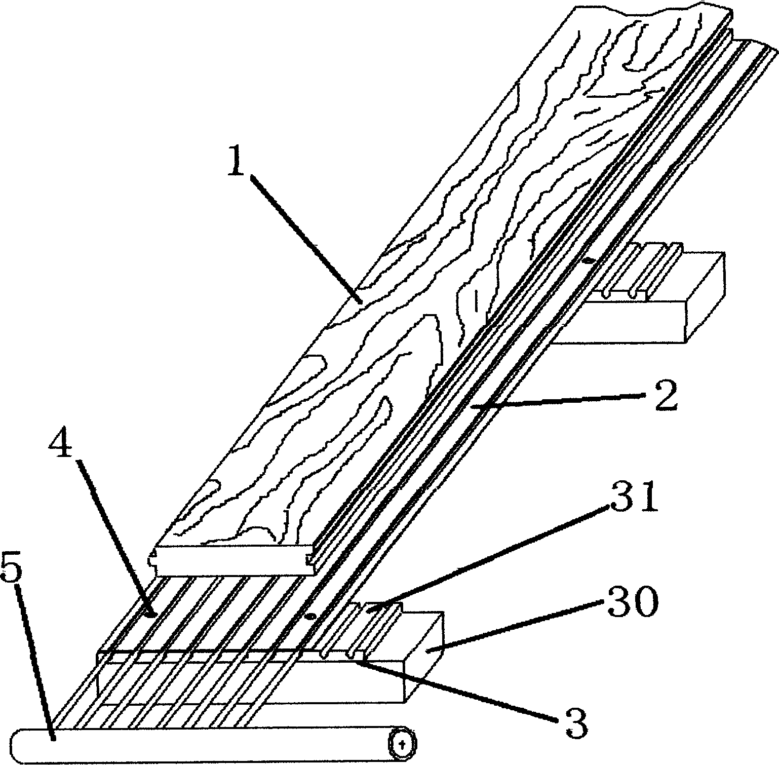
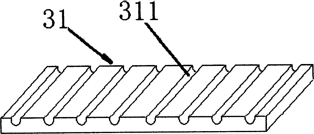
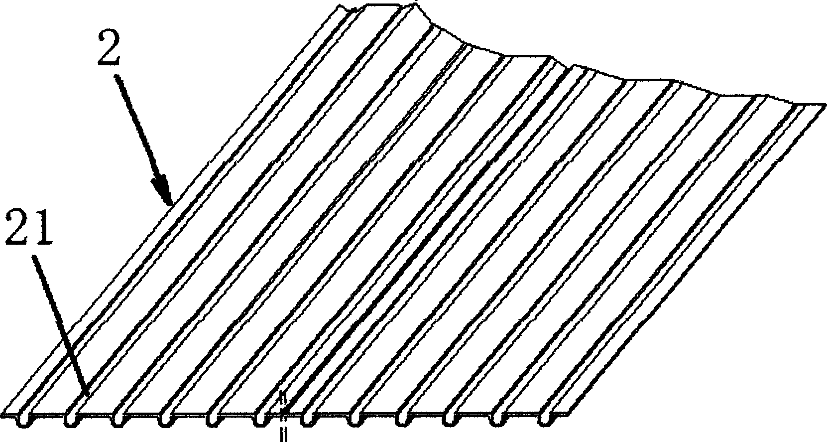
[0021] Such as figure 1 , figure 2 , image 3 with Figure 4 As shown, a new type of floor air conditioner terminal includes a floor 1, a capillary network heat transfer carrier 2, a structural keel 3, and a capillary network 5. The capillary network 5 includes a water inlet pipe 51 and a return pipe 52, and several pipes connected to the water inlet pipe 51 and the return pipe 52. The capillary tubes 53 arranged at equal intervals, the capillary tube network heat conduction carrier 2 is formed with several capillary tube accommodating cavities 21 arranged at equal intervals protruding downwards and capable of accommodating the capillary tubes 53, the capillary tubes 53 are arranged in the capillary tube accommodating cavity 21 and the capillary tubes 53 can transfer energy to the heat conduction carrier 2 of the capillary network when hot water or cold water is supplied. The structural keel 3 includes the keel 30 and the structural pad 31 arranged on the keel. The upper su...

Embodiment 2

[0026] Such as Figure 5 As shown, the difference from Embodiment 1 is that the structural keel 3 is an integrated structure. In this embodiment, the same equally spaced grooves 311 that match the outer wall of the capillary accommodating cavity 21 are directly arranged on the structural keel 3 the upper surface and as a whole. Others are the same as in Embodiment 1, and will not be repeated here.


PUM


Abstract

The invention relates to a novel floor air conditioner terminal which comprises a floor 1, a capillary tube network heat-conducting carrier 2, a structure keel 3 and a capillary tube network 5. The novel floor air conditioner terminal is characterized in that the capillary tube network 5 comprises a water inlet tube 51, a water return tube 52 and a plurality of capillary tubes, the capillary tubes are communicated with the water inlet tube 51 and the water return tube 52 and arranged at equal intervals, a plurality of capillary tube accommodating cavities 21 which protrude downwards, can accommodate the capillary tubes and are arranged at equal intervals are formed in the capillary tube network heat-conducting carrier 2, the capillary tubes 53 arranged in the capillary tube accommodating cavities 21 can transmit energy to the capillary tube network heat-conducting carrier 2 when hot water or cold water is supplied, grooves 311 which are matched with the outer walls of the capillary tube accommodating cavities and arranged at equal intervals are formed in the upper surface of the structure kneel 3, the capillary tube network heat-conducting carrier 2 is laid on the upper surface of the structure kneel 3 and keeps a certain distance from the ground, and the capillary tube network 5 is laid between the floor 1 and the capillary tube network heat-conducting carrier 2. The novel floor air conditioner terminal is usually used with various heat pumps and central ventilation systems thereof in a combined mode, so that a technique utilizing the floor to realize an air conditioning function is realized.

Description

technical field [0001] The invention belongs to the technical field of decoration and decoration materials, and relates to indoor heating and cooling technologies, in particular to a novel floor air conditioner terminal technology for cooling or heating through a capillary network. Background technique [0002] In the prior art, the traditional pavement method of capillary network radiant air conditioner is still the same. First lay the insulation board on the wall or ceiling, then lay the capillary mat on the insulation board, and then smear it with a thickness of about 10mm. The plaster is complex in construction, takes up the height of the floor, and the site is dirty and messy, with heavy humidity; in particular, a complex air humidity adjustment and control system is required, and windows are generally not allowed to be opened during use. Not only the investment is high, but also the energy consumption is high during dehumidification. [0003] At present, there is anot...

Claims


Application Information

Patent Timeline
Patent Type & Authority Applications(China)
IPC IPC(8): F24F1/00
Inventor 李渊李增清
Owner 李渊
Why Eureka
Try Eureka