Underflow energy dissipation structure for fish back type drop bank

A technology for energy dissipation of undercurrent and fish back, which is applied in water conservancy engineering, marine engineering, coastline protection, etc., can solve problems such as building damage and surrounding environmental impact, and achieve the effects of high safety, mitigation of threats, and reduction of pulsating pressure.

Active Publication Date: 2015-03-25
CHINA THREE GORGES CORPORATION
View PDF8 Cites 0 Cited by
  • Summary
  • Abstract
  • Description
  • Claims
  • Application Information

AI Technical Summary

Problems solved by technology

[0005] However, a large number of specific studies and observations have found that after the water flows into the pool, there are backflows and vertical vortexes of different intensities, which cause washing, entrainment, and high dynamic water pressure to cause serious damage to the building, and have different effects on the surrounding environment. degree of influence

Method used


Image

  • Underflow energy dissipation structure for fish back type drop bank
  • Underflow energy dissipation structure for fish back type drop bank
  • Underflow energy dissipation structure for fish back type drop bank

Examples


Embodiment 1

[0046] Embodiment 1 represents the case where the first-stage discharge tank adopts a multi-stream discharge mode, that is, a multi-stream outflow mode, and the second-stage fish-back discharge tank adopts a continuous type.

Embodiment 2

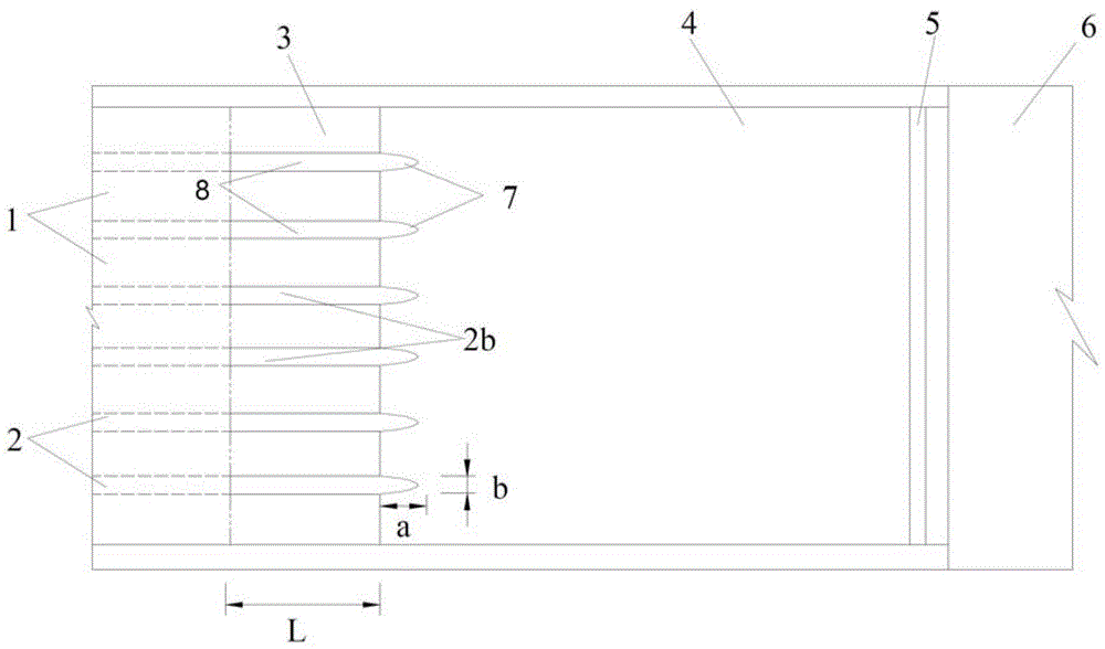
[0047] Embodiment 2 represents the case where the first-stage discharge tank adopts a multi-stream discharge mode, that is, a multi-stream outflow mode, and the second-stage fish-back discharge tank adopts an interval type.

[0048] These embodiments are also applicable to the continuous discharge mode of the upstream discharge tank (primary discharge tank), that is, the continuous outflow mode.

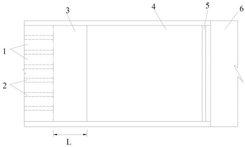
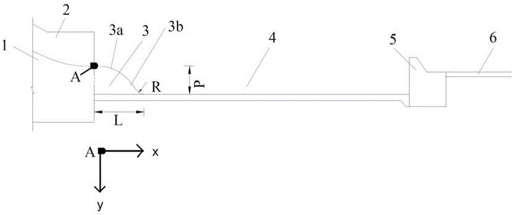
[0049] In Example 1, see figure 1Shown is a schematic plan view of the structure of the fish-back type falling sill and bottom flow energy dissipator in Example 1. The present invention provides a new type of fish-back type falling sill and bottom flow energy dissipation structure. , the chute partition wall 2, the secondary fish-back chute 3, the stilling pool 4, the tail sill of the stilling pool 5 and the downstream apron 6.

[0050] Wherein, the secondary fish-back type discharge tank 3 adopts a continuous type, the front end of the secondary fish-back type discharge tank 3 is h...


PUM


Abstract

The invention relates to an underflow energy dissipation structure for a fish back type drop bank. The underflow energy dissipation structure comprises a first stage flow discharge groove, a discharge chute partition wall, a second stage fish back type flow discharge groove, an absorption basin, an absorption basin tail bank and a downstream protection apron, wherein an elevation difference exists between the tail end of the first stage flow discharge groove and the absorption basin; the downstream of the first stage flow discharge groove is connected with the top end of the second stage fish back type flow discharge groove; the tail part of the second stage fish back type flow discharge groove is connected with the absorption basin, and the bottom surface of the second stage fish back type flow discharge groove is overlapped with a bottom plate of the absorption basin; and the second stage fish back type flow discharge groove adopts a continuous type and a separated type. The underflow energy dissipation structure for the fish back type drop bank is characterized in that an underflow energy dissipation effect is reserved, hydraulics indicators such as pulse pressure, bottom velocity and the like of the absorption basin are effectively reduced, and at the same time, threats of backflows to a dam site are relieved; the underflow energy dissipation structure has the advantages of stable in-basin flow state, high energy dissipation efficiency and energy dissipation construction safety, small tail water fluctuation, low flood discharge atomization and the like; and the structure is simple, and a wide application prospect is provided.

Description

technical field [0001] The invention relates to the field of flood discharge and energy dissipation facilities, in particular to a fish-back type falling sill bottom flow energy dissipation structure capable of improving the hydraulic index of a stilling pool. Background technique [0002] The main energy dissipation methods in the downstream of the high dam include underflow energy dissipation, deflecting flow energy dissipation, surface flow energy dissipation and force-reducing bucket energy dissipation. Among them, underflow energy dissipation is a relatively mature energy dissipation method, which has the characteristics of stable flow state in the pond, It has the advantages of high energy dissipation efficiency, small tail water fluctuation, and small impact of flood discharge atomization. [0003] However, due to the bottom flow energy dissipation method, the jet flow is close to the bottom, and the hydraulic index of the bottom plate of the stilling tank is very hig...

Claims


Application Information

Patent Timeline
Patent Type & Authority Patents(China)
IPC IPC(8): E02B8/06
Inventor 戴会超郑铁刚张培培杨文俊牛志攀
Owner CHINA THREE GORGES CORPORATION
Why Eureka
Try Eureka