
Catheter for lacrimal passage

A technology for placing tubes and lacrimal ducts, applied in ophthalmic surgery, etc., can solve problems such as nasal mucosa irritation, difficulty in lacrimal duct implantation, and strong discomfort

Inactive Publication Date: 2013-11-27
潘东艳
View PDF7 Cites 2 Cited by
  • Summary
  • Abstract
  • Description
  • Claims
  • Application Information

AI Technical Summary

Problems solved by technology

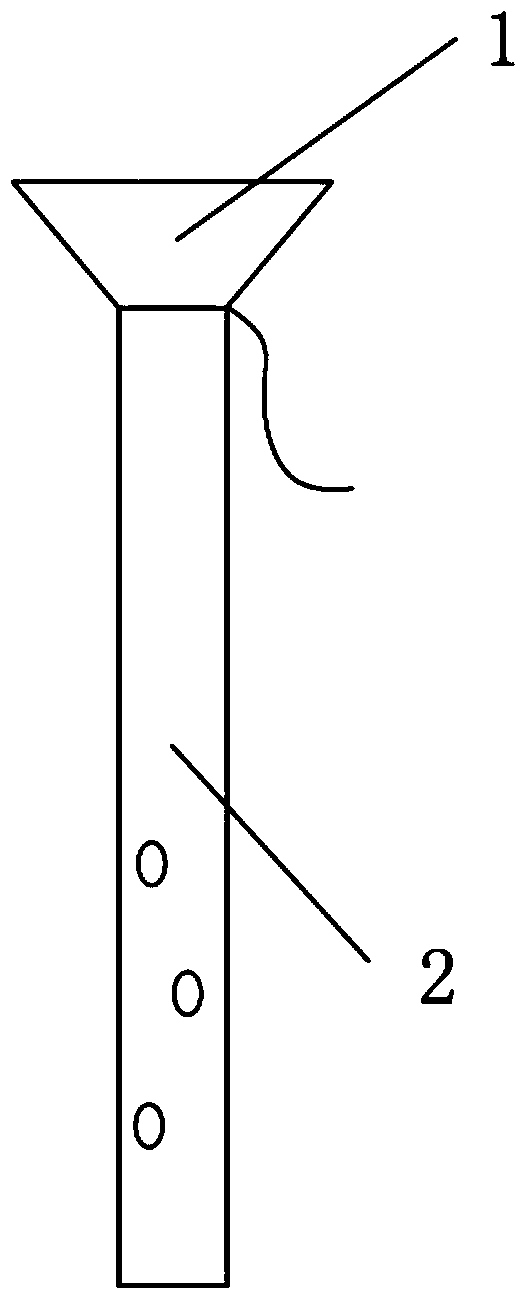
[0002] Lacrimal tubes are used to treat lacrimal diseases, such as dacryocystitis, etc. There are roughly two types of lacrimal tubes. One is the metal tube used in the early stage. The material of the metal tube is relatively hard. When the length of the metal tube is longer When placed in the nasal cavity, the discomfort is very strong, and the nasal mucosa is irritated, resulting in granulation hyperplasia. At present, it is popular to use the lacrimal cannula made of silica gel, but the lacrimal cannula made of pure silica gel has poor shaping effect. Lacrimal catheters such as figure 1 As shown, the lacrimal sac part 1 is a hollow cavity with an opening on its side or upper end. The lacrimal sac part 1 is in the lacrimal sac of the human body, and the lacrimal sac part 1 is used to stretch the lacrimal sac. Tears, this kind of lacrimal duct is difficult to implant, and the patient suffers a lot, and because the tear has a certain viscosity, a single opening is not conducive to tear collection, and because the tear collection effect is poor, the nasolacrimal duct 2 needs to be installed drainage hole

Method used


Image

  • Catheter for lacrimal passage
  • Catheter for lacrimal passage
  • Catheter for lacrimal passage

Examples


Embodiment Construction

[0019] In order to understand the technical content of the present invention more clearly, the following embodiments are given for detailed description.

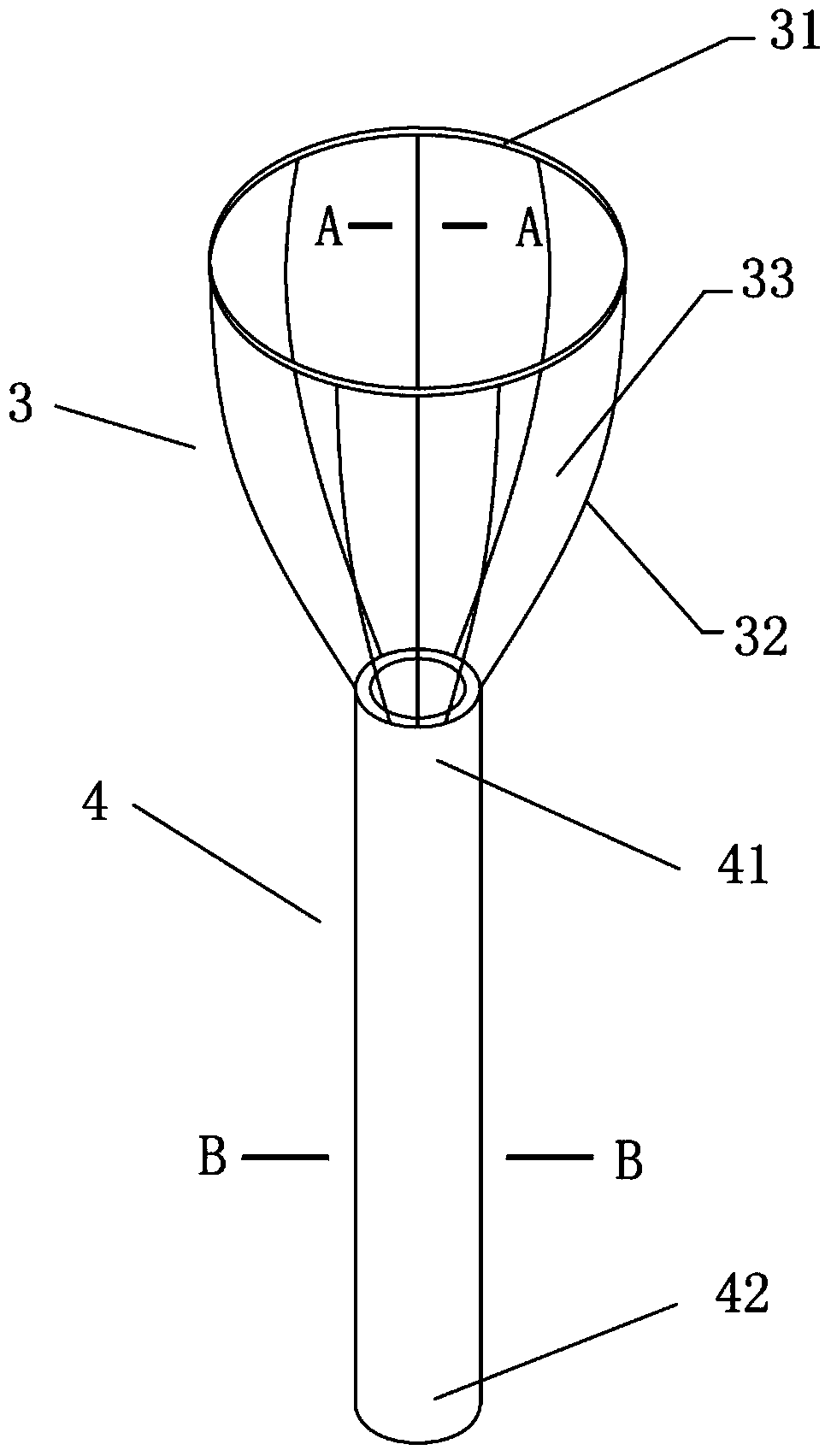
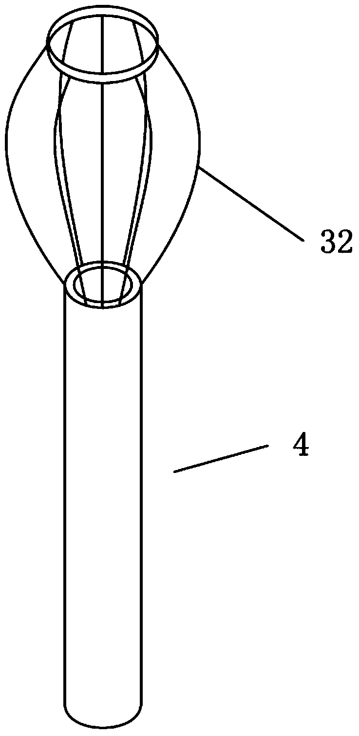
[0020] The lacrimal duct cannula includes a lacrimal sac portion 3 and a nasolacrimal duct 4. The lacrimal sac portion 3 is located at the upper end of the nasolacrimal duct 4. The lacrimal sac portion 3 includes at least three elastic wires 32. The lower end of the elastic wires 32 is connected to the nasolacrimal duct. The upper end of 2 is fixedly connected, the upper end of the elastic wire 32 is fixedly connected with the fixing ring 31, and the elastic wire 32 is distributed along the circumferential direction of the fixing ring 31, and the inner space formed by the elastic wire 32 and the fixing ring 31 is the lacrimal sac portion 3, A drainage gap 33 is formed between the elastic wire 32 and the adjacent elastic wire 32; the elastic wire 32 is arc-shaped, the elastic wire 32 is a metal wire 5, and the surface of the e...


PUM


Abstract

The invention relates to a catheter for a lacrimal passage. The catheter comprises a lacrimal sac part and a naso-lacrymal duct, wherein the lacrimal sac part is located at the upper end of the naso-lacrymal duct and comprises at least three elastic wires. The lower ends of the elastic wires are fixedly connected with the upper end of the naso-lacrymal duct, while the upper ends of the elastic wires are fixedly connected with a fixed ring, and drainage gaps are formed between the adjacent wires. The elastic wires are metal wires which are arc-shaped, and a silica gel layer is formed on the surface of each elastic wire. With the adoption of the catheter for the lacrimal passage in the structure, the lacrimal sac part is made of memory metals. When the lacrimal sac part is implanted, the elastic wires are extruded by the lacrimal passage to be straightened, so that the catheter is easier to implant, and pain of the patient is less. When the lacrimal sac part reaches the lacrimal sac of the human body, the elastic wires are recovered to the original expanded state to effectively dilate the lacrimal sac part without irritating the mucosa. The catheter for the lacrimal passage has a very good drainage effect, and tear is introduced to the naso-lacrymal duct through the drainage gaps among the elastic wires, so that the catheter drains thoroughly and no residual tear is left in the lacrimal sac.

Description

technical field [0001] The invention relates to the technical field of medical equipment, in particular to a lacrimal canal placement. Background technique [0002] Lacrimal duct catheters are used to treat lacrimal duct diseases, such as dacryocystitis. There are two types of lacrimal duct catheters. One is the metal tube used in the early stage. The material of the metal tube is harder. When the length of the metal tube is longer When placed in the nasal cavity, the discomfort is very strong, and due to the irritation to the nasal mucosa, granulation hyperplasia occurs. At present, the use of lacrimal duct catheterization made of silicone material has become popular, but the lacrimal duct catheterization effect of pure silicone material is poor. Traditional lacrimal duct catheterization figure 1 As shown, the hollow cavity of the lacrimal sac part 1 has an opening on its side or upper end, the lacrimal sac part 1 is in the lacrimal sac of the human body, the lacrimal sac ...

Claims


Application Information

Patent Timeline
IPC IPC(8): A61F9/007
Inventor 潘东艳
Owner 潘东艳
Learn More