
Infrared probe

An infrared probe and infrared receiver technology, which is applied in the field of infrared probes, can solve the problems of inability to accurately define the boundary of the mouse nose entry hole, errors in time and frequency, and achieve the effect of rapid and sensitive data recording

Inactive Publication Date: 2013-11-27
LANZHOU UNIVERSITY
View PDF7 Cites 0 Cited by
  • Summary
  • Abstract
  • Description
  • Claims
  • Application Information

AI Technical Summary

Problems solved by technology

[0003] Before using the tester to test the mouse's sense of smell, it is necessary to adjust the sensitivity of each capacitance monitor of the instrument. Since the output signal of the monitor is an analog signal, it is not possible to accurately define the boundary of the mouse nose entry hole. Record There will be errors in the time and number of probes to the mouse

Method used


Image

  • Infrared probe
  • Infrared probe
  • Infrared probe

Examples


Embodiment Construction

[0016] The present invention will be described in detail below with reference to the accompanying drawings. The description in this part is only exemplary and explanatory, and should not have any limitation on the protection scope of the present invention.

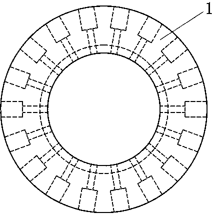
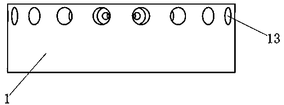
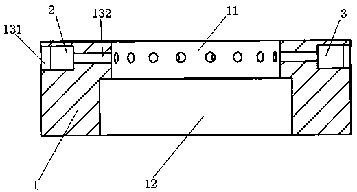
[0017] Such as Figure 1-4 An infrared probe shown includes a mounting table 1, an infrared transmitter 2 and an infrared receiver 3. The mounting table 1 is cylindrical.

[0018] The mounting table 1 is made of aluminum and has a cylindrical structure. The central hole is a stepped hole. The inner diameter of the smaller part 11 of the central hole is 36 mm, and the inner diameter of the larger part 12 of the central hole is 41mm. The larger part 12 of the hole is used to fit the top of the scent bottle below it. The outer diameter of the mounting table 1 is 66 mm and the thickness is 20 mm. The cylindrical wall of the smaller part 11 surrounding the central hole of the mounting platform 1 is provided with a through hole 13 ...


PUM


Abstract

The invention discloses an infrared probe comprising a cylindrical mounting table, an infrared transmitter and an infrared receiver. A plurality of pairs of through holes extending radially along the mounting table are evenly distributed around the cylindrical wall of the mounting table, and the mounting holes in each pair are opposite to each other and used for mounting the infrared transmitter and the infrared receiver. The infrared probe has the advantage that an olfactory tester is ensured to record data rapidly and sensitively.

Description

Technical field [0001] The invention relates to the technical field of olfactory testers, in particular to an infrared probe. Background technique [0002] At present, the monitor of the mouse orifice olfactory tester for scientific experiments is a capacitive electrode made according to Kirchhoff's current law. When the animal approaches the monitor, the charge inside the capacitor will be transferred to produce an analog signal. These signals are collected by the analog signal acquisition card and transmitted to the computer, and then the information is converted into the required data through software analysis. [0003] Before using this tester to test the sense of smell of mice, the sensitivity of each capacitance monitor of the instrument needs to be adjusted. Because the output signal of the monitor is an analog signal, it is not possible to accurately define the boundary of the mouse nose entry hole. Record There will be errors in the time and number of probes to the mouse....

Claims


Application Information

Patent Timeline
Patent Type & Authority Applications(China)
IPC IPC(8): A61B5/00
Inventor 侯一平邵玉峰赵鹏李婧董朝玉解俊樊王灿王海亮戴丽蓉
Owner LANZHOU UNIVERSITY
Learn More