
bracket with nut

A nut and bracket technology, applied in the direction of nuts, screws, bolts, etc., can solve the problems of fixing, unable to fit into the parts that cannot be fastened, etc., and achieve the effect of ensuring the tightening force and improving the tightening rigidity.

Inactive Publication Date: 2015-07-29
HONDA MOTOR CO LTD
View PDF9 Cites 0 Cited by
  • Summary
  • Abstract
  • Description
  • Claims
  • Application Information

AI Technical Summary

Problems solved by technology

At this time, if the width of the rib 01b is smaller than the diameter of the head 03a of the bolt 03, the head 03a of the bolt 03 cannot be fitted into the rib 01b and the fastened member cannot be fixed to the bottom surface of the rib 01b. question

Method used


Image

  • bracket with nut
  • bracket with nut
  • bracket with nut

Examples


no. 1 Embodiment approach

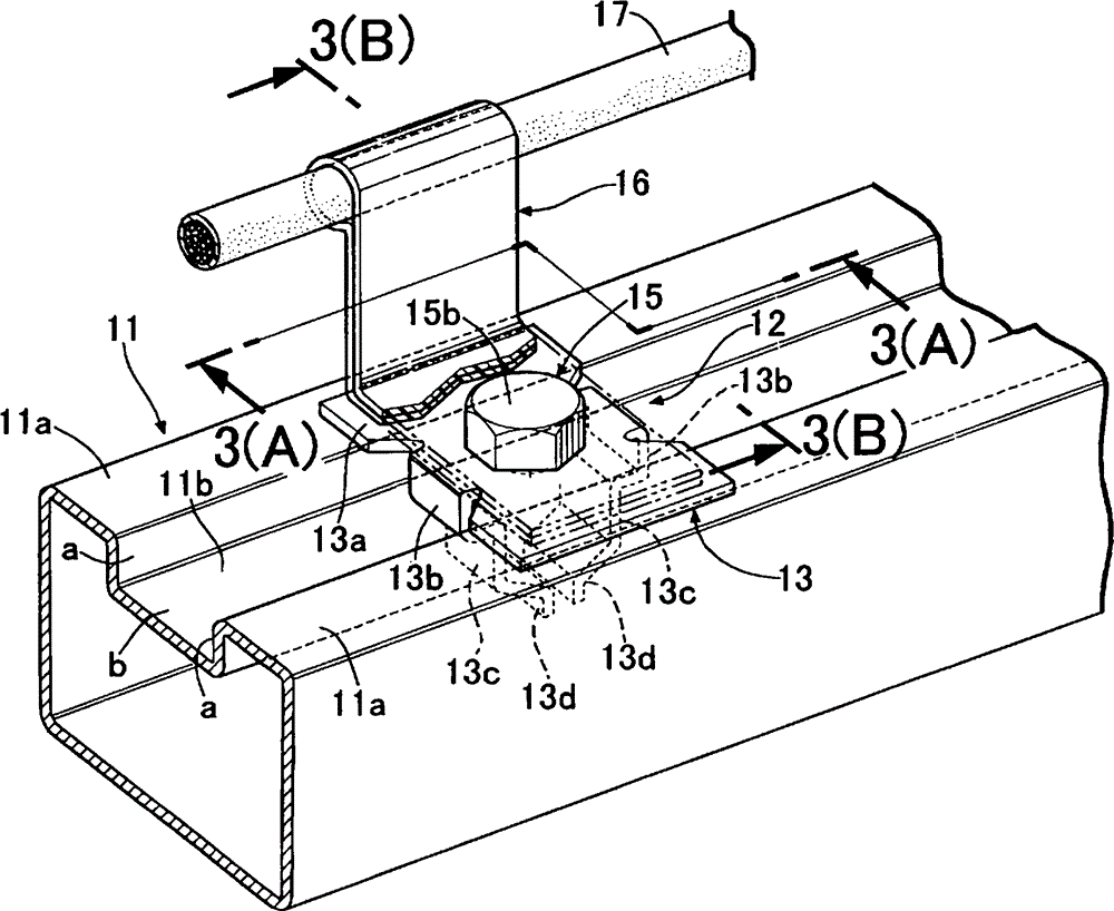
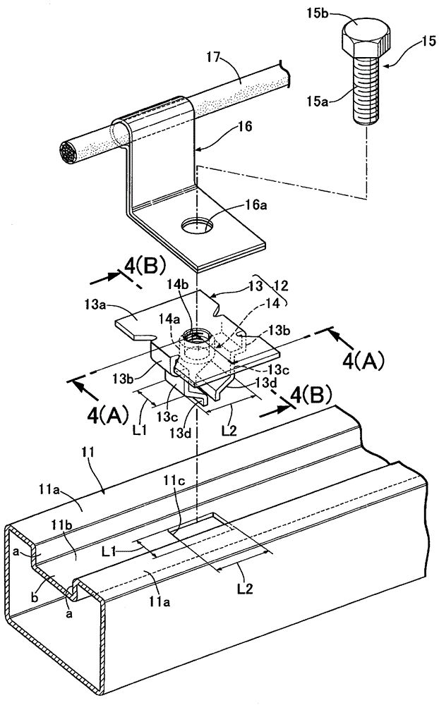
[0048] Such as figure 1 and figure 2 As shown, for example, the body frame 11 of an automobile is a component that constitutes a rectangular closed section, and on one of its four faces, a square groove sandwiched by two surfaces 11a, 11a is formed along the length direction of the body frame 11. Shaped ribs 11b. The rib 11b has a pair of side walls a, a and a bottom wall b sandwiched between the side walls a, a, and a rectangular opening 11c is formed on the bottom wall b.

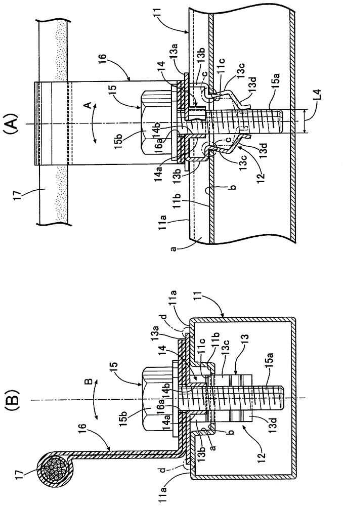
[0049] Such as Figure 1 ~ Figure 4 As shown, the bracket 12 with a nut installed in the opening 11c of the bottom wall b of the rib 11b of the vehicle body frame 11 is composed of a bracket portion 13 and a nut portion 14 which are integrally formed. The bracket portion 13 is formed by bending a single metal plate, and has a substantially rectangular plate-shaped base portion 13a; The first leg portion 13b, 13b of font-shaped section; A pair of second leg portion 13c, 13c extending linearly downwar...

no. 2 Embodiment approach

[0061] In the second embodiment, the depth of the rib 11 b of the vehicle body frame 11 (the height of the side walls a, a) is increased compared to the first embodiment. Also in such a case, it can cope only by extending the 1st leg part 13b, 13b of the bracket 12 with a nut. If the depth of the rib 11b is increased, the bracket 12 with the nut is likely to fall when a moment in the A direction or a moment in the B direction acts, but it can be prevented by the same function as the first embodiment. The toppling of the bracket 12.

[0062] Next, based on Image 6 A third embodiment of the present invention will be described.

no. 3 Embodiment approach

[0064] In the first and second embodiments, the bracket portion 13 of the nut-equipped bracket 12 is formed of a metal plate, but in the third embodiment, the bracket portion 13 is integrally formed of synthetic resin. Furthermore, a metal nut portion 14 is fitted into the base portion 13 a of the bracket portion 13 . According to this third embodiment, the cylindrically swollen portions of the third leg portions 13d, 13d are expanded by the shaft portion 15a of the bolt 15, thereby, similarly to the first and second embodiments, the first leg portion 13b, 13b and the bent parts c, c between the second leg parts 13c, 13c are engaged with the edge of the opening 11c of the bottom wall b of the rib 11b, so that the bracket 12 with nuts is fixed on the body frame 11. .


PUM


Abstract

A bracket with nut (12) fitted into an interior of a groove-shaped bead (11b) formed on a surface of a member (11) includes a nut part (14) into which a bolt (15) is screwed, and a bracket part (13) that supports the nut part (14) and is retained by an opening (11c) formed in a bottom wall (b) of the bead (11b). The bracket part (13) includes the base portion (13a) and a first to third leg portions (13b, 13c, 13d), and if the bolt (15) is screwed into the nut part (14) in a state in which the second leg portions (13c) and the third let portions (13d) are inserted into the opening (11c), the third leg portions (13d) are pushed by the bolt (15) to thus open out the second leg portions (13c) on the interior side of the opening (11c), thus retaining the bracket part (13) so as not to fall out of the opening (11c) and thereby enabling another member (16) to be secured to the base portion (13a) of the member (11) by screwing the bolt (15) into the nut part (14). This enables a nut equipped with a flange to be provided that can easily and reliably fix a member to the surface of another member having a groove-shaped bead formed thereon.

Description

technical field [0001] The present invention relates to a bracket with a nut mounted inside a groove-shaped rib formed on the surface of a component. Background technique [0002] According to the following patent document 1, it is known that when a piercing nut (pierce nut) is driven into the wall surface of a closed-section aluminum alloy extruded profile from the hollow interior side to fix it, in order to firmly fix the piercing nut to the aluminum alloy In the wall surface of the alloy extruded profile, the plate thickness of the wall surface into which the piercing nut is driven is greater than the plate thickness of other parts. [0003] prior art literature [0004] patent documents [0005] Patent Document 1: Japanese Patent Laid-Open No. 2010-18061 Contents of the invention [0006] However, in the invention described in the above-mentioned Patent Document 1, the following problems arise when the fastened member is fastened to the surface of the member on whic...

Claims


Application Information

Patent Timeline
Patent Type & Authority Patents(China)
IPC IPC(8): F16B37/02F16B37/00F16B37/04F16B2/08H02G3/30
CPCF16B37/02F16B33/002F16M13/02F16B29/00F16B37/045H02G3/30
Inventor 铃木庸一郎
Owner HONDA MOTOR CO LTD
Learn More