Dynamic dummy load with simple structure

A technology with simple structure and dummy load, applied in the direction of output power conversion device, electrical components, etc., can solve the problems of high cost, complicated circuit, unsuitable for low-end power supply, etc., and achieve the effect of reducing loss and easing the trend of output voltage drop.

Inactive Publication Date: 2013-11-20
南京国睿新能电子有限公司
View PDF7 Cites 9 Cited by
  • Summary
  • Abstract
  • Description
  • Claims
  • Application Information

AI Technical Summary

Problems solved by technology

The advantage of this method is that it can automatically switch the dummy load under light load conditions, but the disadvantage is also that the circuit is complex, the cost is high, and it is not suitable for low-end power supplies.

Method used


Image

  • Dynamic dummy load with simple structure
  • Dynamic dummy load with simple structure
  • Dynamic dummy load with simple structure

Examples


Embodiment

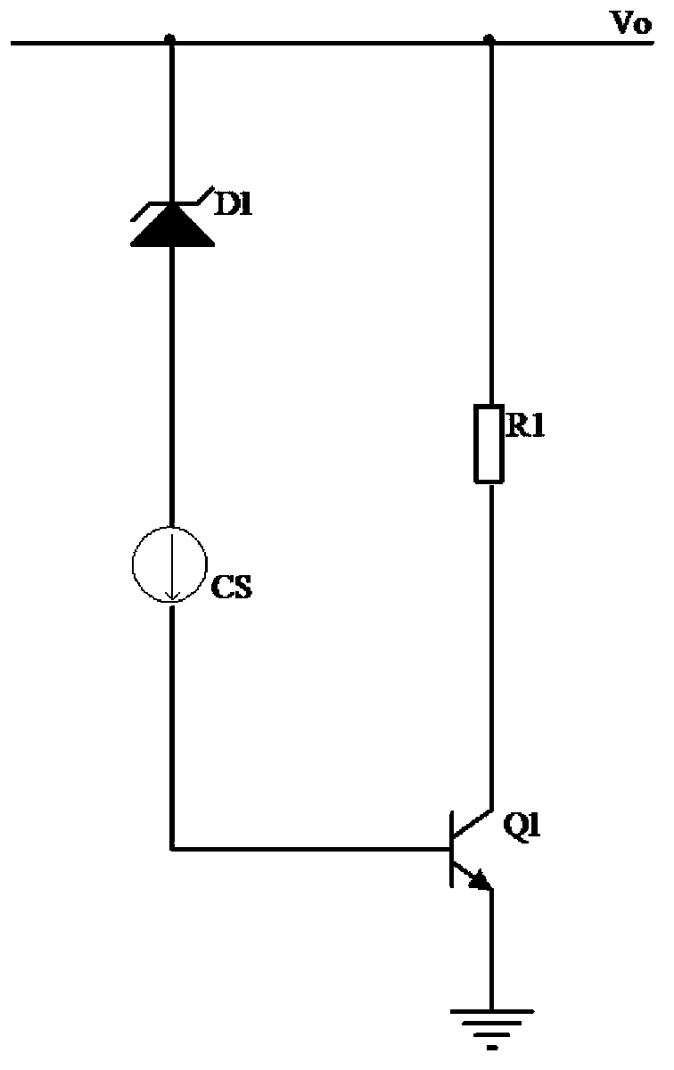
[0064] Such as Figure 4 As shown, the current source SC is composed of a PNP transistor Q2 and a resistor R3,

[0065] Ic of PNP transistor Q2 Q2 The magnitude of the current is Ic Q 2 = Vbe _ Q 2 R 2 × h F E _ Q 2

[0066] where h FE_Q2 Is the magnification of the transistor Q2.

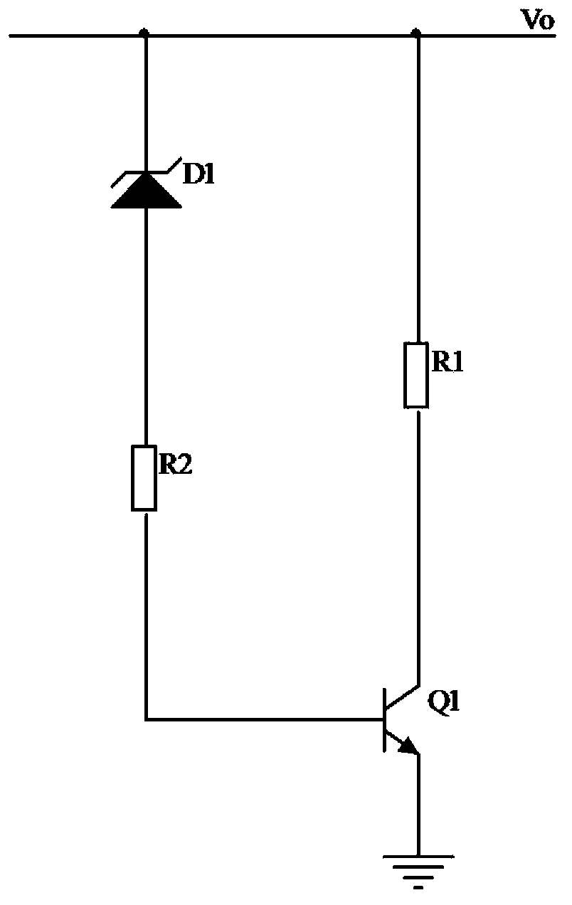
[0067] The dynamic dummy load with a simple structure includes a voltage stabilizing diode D1, a control switch transistor Q1, a PNP transistor Q2, a resistor R3 and a dummy load resistor R1.

[0068] The cathode of Zener diode D1 is connected to the output voltage V 0 connection, the anode is connected to the PNP transistor Q2;

[0069...


PUM


Abstract

The invention relates to a dynamic dummy load with a simple structure. The dynamic dummy load with the simple structure comprises a voltage sampling unit, a control unit, a dummy load body and a control switch, wherein the voltage sampling unit is used for collecting output voltage; the control unit is used for comparing output voltage and threshold value voltage and driving the control switch to be switched on and off; if the output voltage exceeds the threshold value voltage, the control switch is driven to be switched on, the dummy load is connected to the output voltage in parallel, and the dummy load is connected to work; if the output voltage is lower than the threshold value voltage, the control switch is switched off, and the dummy load body is cut off. According to the dynamic dummy load with the simple structure, which is disclosed by the invention, the output dummy load is dynamically loaded and cut off in a low-cost mode, and the dummy load loss can be effectively reduced. In addition, when the output voltage is low, the dummy load is automatically cut off, and the output voltage lowering tendency is objectively alleviated.

Description

technical field [0001] The invention relates to a dynamic dummy load, in particular to a dynamic dummy load with simple structure. Background technique [0002] Power products are widely used in work and life. In order to meet the regulation requirement and avoid performance degradation caused by the power supply being completely unloaded, many power supplies have their own dummy loads. [0003] Generally, the dummy load only works when the output external load is completely unloaded. At this time, because the output is completely unloaded, the output voltage may be too high. This phenomenon is especially obvious on low-cost multi-output power supplies. And when the output external load is greater than the dummy load power, the dummy load is no longer needed. [0004] The dummy load in the traditional sense is generally a resistive load connected in parallel to the output port. However, because it is always connected in parallel at the output end, it is always consuming e...

Claims


Application Information

Patent Timeline
IPC IPC(8): H02M1/32
Inventor 张勇焦伟光
Owner 南京国睿新能电子有限公司
Why Eureka
Try Eureka