Monitoring device of automatic reactive compensation system for high-low voltage power distribution network

A compensation system and monitoring device technology, applied in reactive power adjustment/elimination/compensation, flexible AC transmission system, cooling/ventilation of substation/switchgear, etc., can solve the lack of real-time monitoring of distribution network, backward algorithm, lack of Communication and other issues, to achieve the effect of improving monitoring accuracy and comprehensiveness, improving accuracy and efficiency, and extending service life

Active Publication Date: 2013-11-20
四川晨龙航天电器设备有限公司
View PDF5 Cites 8 Cited by
  • Summary
  • Abstract
  • Description
  • Claims
  • Application Information

AI Technical Summary

Benefits of technology

This patented technology helps improve the performance and reliability of an electricity supply grid with multiple components such as voltage sources (SVs) or generators connected together. It uses advanced sensors that can detect various operational conditions like current flowing from one source to another without interrupting their normal functioning. By doing this, it provides more accurate data for efficient energy management while also extending its lifespan beyond what was previously possible due to external factors affecting how well they work properly.

Problems solved by technology

Technics Problem addressed in this patents include improving power supply reliableness during periods when AC voltages drop below certain levels due to various causes such as lighting strikes or other electrical disturbances like faults. However, existing methods have limited effectiveness at addressing these issues with varying degrees of success depending upon how well they can handle different situations accurately despite their own characteristics.

Method used


Image

  • Monitoring device of automatic reactive compensation system for high-low voltage power distribution network
  • Monitoring device of automatic reactive compensation system for high-low voltage power distribution network
  • Monitoring device of automatic reactive compensation system for high-low voltage power distribution network

Examples


Embodiment Construction

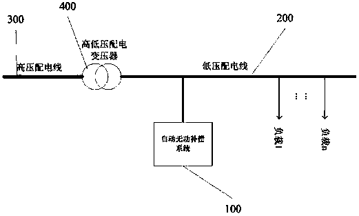
[0020] see figure 1 , the monitoring device 100 of the automatic reactive power compensation system of the high and low voltage distribution network is used for the reactive power compensation system in the high and low voltage distribution network, in a typical high and low voltage distribution network, including the high voltage distribution line 300, the high and low voltage distribution Electric transformer 400, low-voltage distribution line 200, wherein the high-voltage distribution line 300 is located at the high-voltage side of the high-voltage distribution transformer 400, the low-voltage distribution line 300 is located at the low-voltage side of the high-voltage distribution transformer 400, and the low-voltage distribution line 200 is connected to There are multiple loads 1-n, typically these loads are resistive and inductive. The function of the automatic reactive power compensation device 100 of the present invention is to compensate the reactive power consumed by...


PUM


Abstract

The invention relates to a monitoring device of an automatic reactive compensation system for a high-low voltage power distribution network. The monitoring device comprises a power distribution network operation data monitoring module and an SVG module operation data monitoring module, wherein the power distribution network operation data monitoring module transmits operation parameters of the power distribution network to an SVG control module via a communication bus in real time; a temperature detection unit of the SVG module operation data monitoring module transmits detected real-time temperature values of all parts of the SVG control module to the SVG control module via a communication bus in real time; a thyristor switch capacitor bank operation parameter monitoring unit of the SVG module operation data monitoring module is used for monitoring whether a capacitor bank operates within a normal working region; a capacitor bank thyristor switch monitoring unit of the SVG module operation data monitoring module monitors the on/off state of a thyristor switch in real time, and is used for monitoring whether the thyristor switch operates normally as per a thyristor switching signal sent out by the SVG control module.

Description


Claims


Application Information

Patent Timeline
Owner 四川晨龙航天电器设备有限公司
Why Eureka
Try Eureka