Laser designator and optical input device
A laser pointer, optical input technology, applied in the input/output process of data processing, optics, instruments, etc., can solve the problem of not suitable for optical touch panel systems with non-self-recovery materials
- Summary
- Abstract
- Description
- Claims
- Application Information
AI Technical Summary
Problems solved by technology
Method used
Image

Examples
no. 1 example
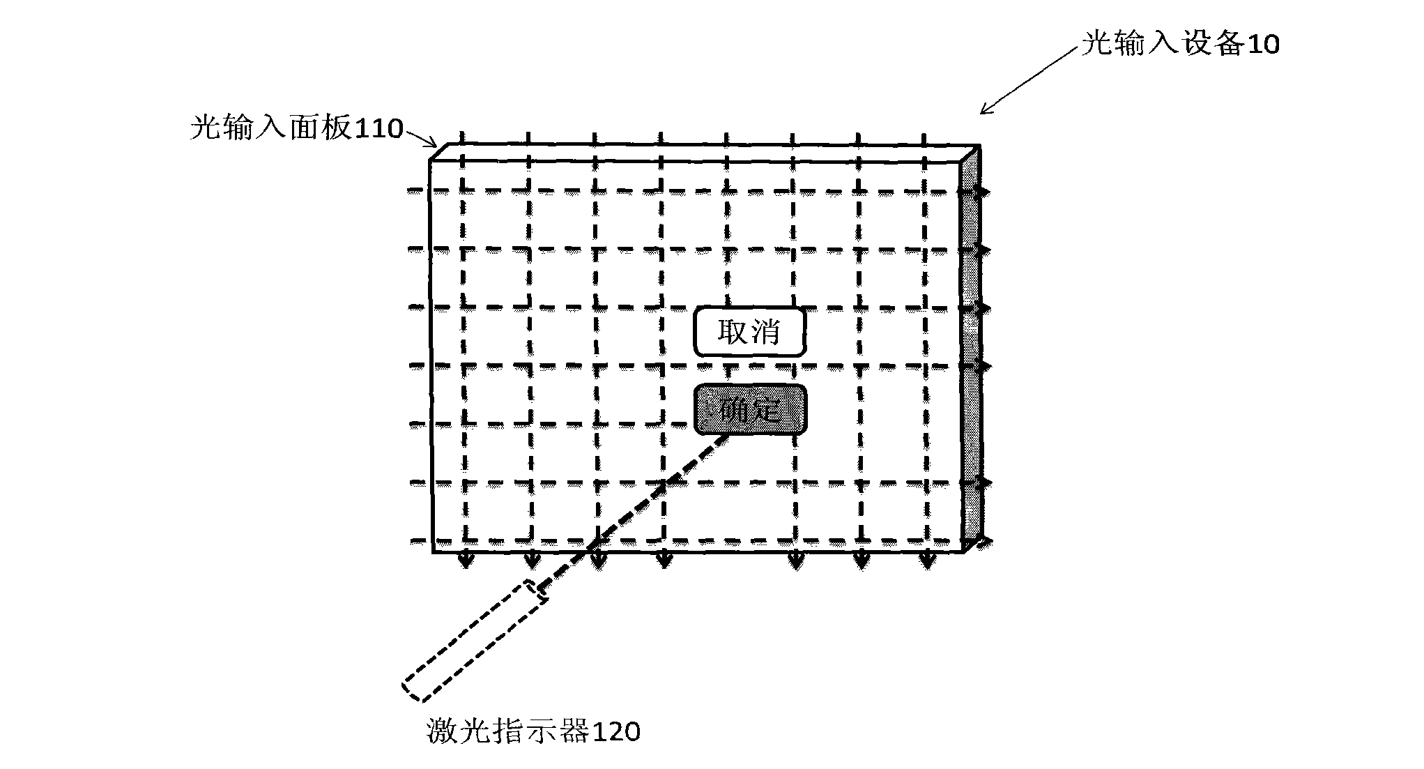
[0044] figure 1 is a schematic diagram showing the optical input device 10 according to the first embodiment of the present invention.
[0045] Such as figure 1 As shown, the optical input device 10 includes an optical input panel 110 and a laser pointer 120 .
[0046] The light input panel may be a transparent panel comprising light sensitive material. The photosensitive material may include: any one of photochromic material, photorefractive material and photodeformable material.
[0047] When the light input panel 110 is placed in front of a display screen, the user can see the content displayed on the display screen. As an example, in figure 1 shows that two buttons to be indicated are displayed on the display screen: an OK button and a Cancel button.
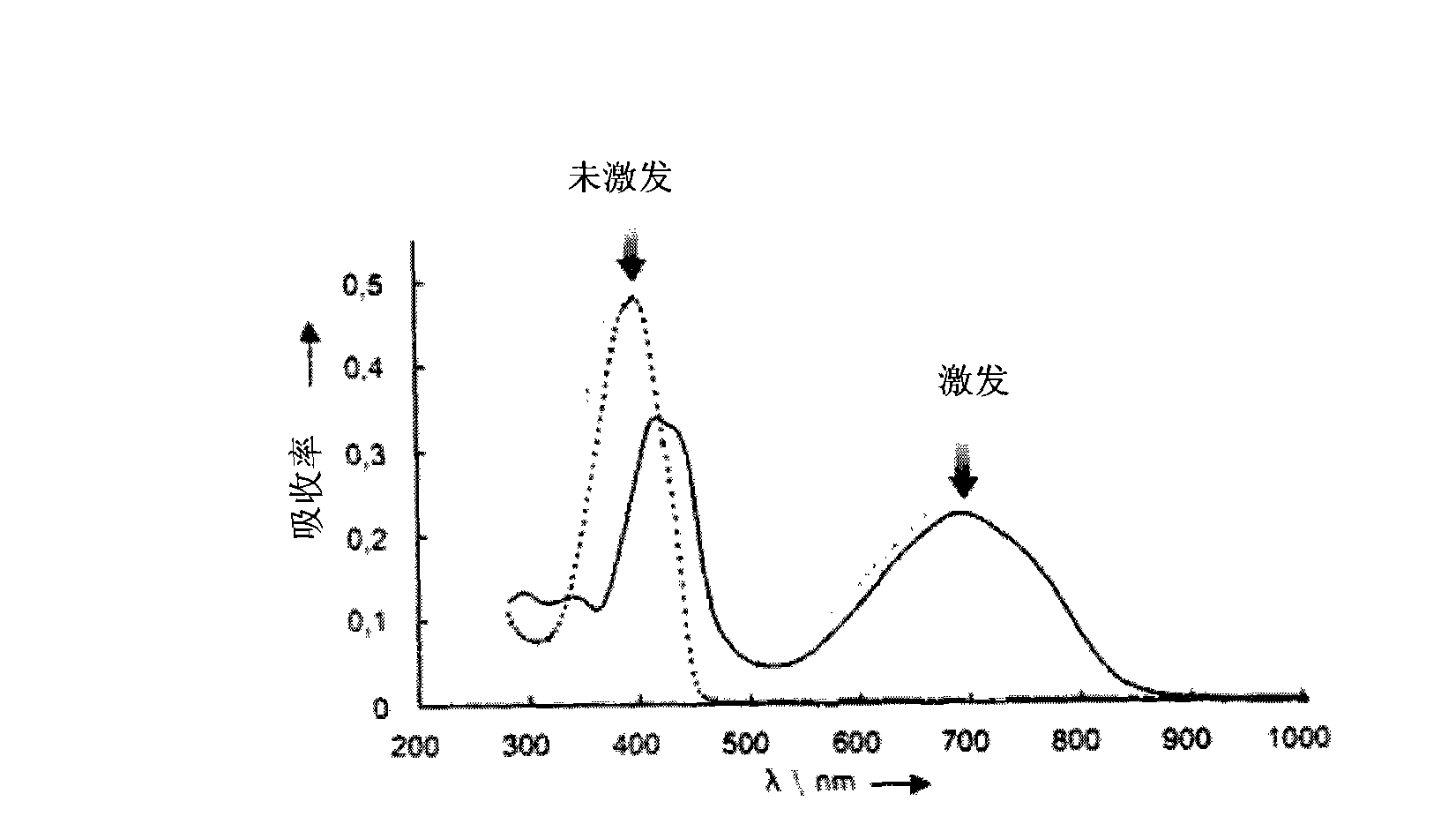
[0048] As an example, in this embodiment, the photosensitive material is composed of bisthiophen-3-yl-perfluorocyclopentene.
[0049] figure 2is a schematic diagram showing the optical properties of this photosensiti...
no. 2 example
[0065] Figure 5 is a block diagram showing the structure of the laser pointer 500 according to the second embodiment of the present invention.
[0066] Such as Figure 5 Therefore, the structure of the laser pointer 500 is similar to that of the laser pointer 300 according to the first embodiment of the present invention, except that the bandpass filter 350 is replaced by a half mirror 550 .
[0067] The ring-shaped 700nm light beam is incident on the half-mirror 550, part of it is transmitted through, and part of it is reflected. Similarly, the 400nm light beam is incident on the half-mirror 550, part of it is transmitted and part of it is reflected. The transmitted 700nm beam combines with the reflected 400nm beam to form a coaxial beam as in the first embodiment.
no. 3 example
[0069] Figure 6 is a block diagram showing the structure of the laser pointer 600 according to the third embodiment of the present invention.
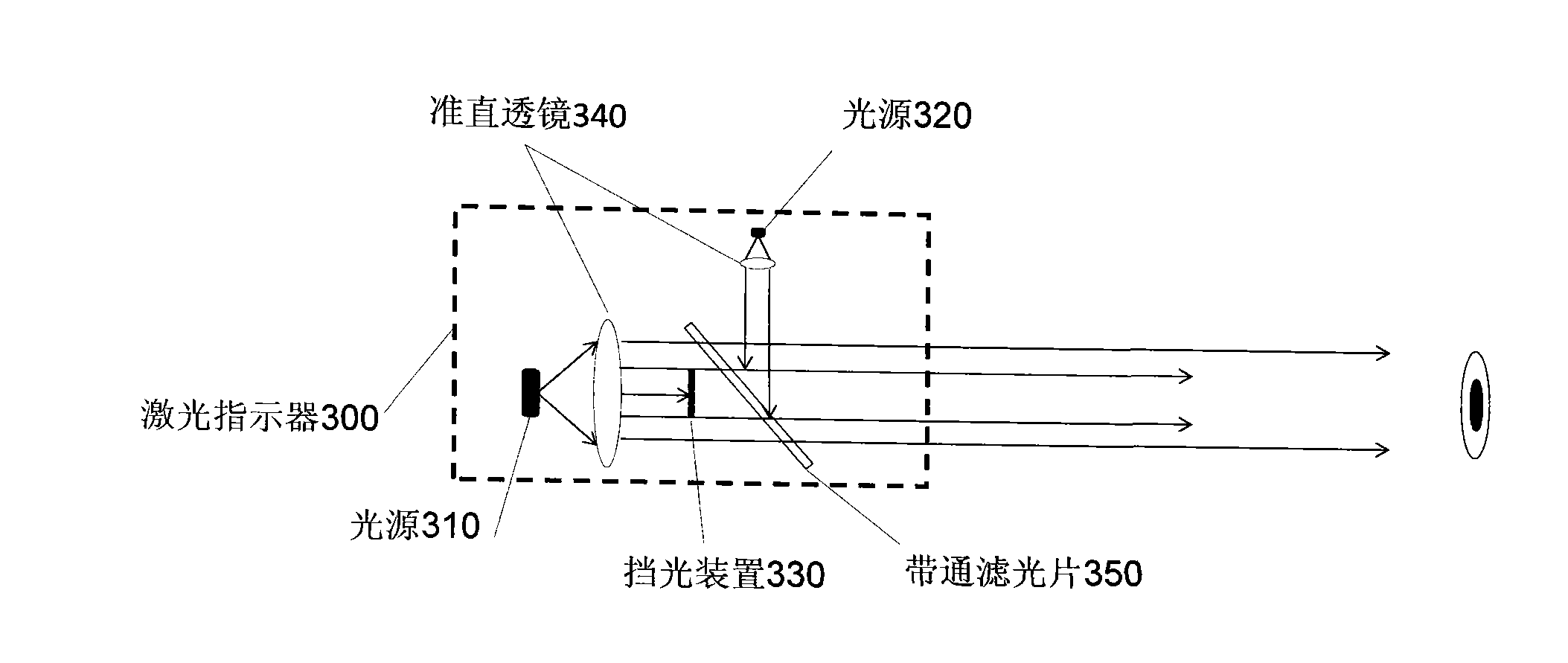
[0070] As shown in the figure, the laser pointer 600 according to the third embodiment includes: a light source 610 and a light source 620 ; a light blocking device 630 ; and an optical train 640 .
[0071] The light source 610, the light source 620, and the light blocking device 630 are the same as those in the laser pointers according to the first and second embodiments.
[0072] In the laser pointer 600, the light emitted by the light source 610 and the light source 620 are collimated and travel in parallel. The optical path combiner includes an optical train 640, including a mirror on the optical path of the 400nm light beam and a bandpass filter on the optical path of the 700nm light beam. The 400nm light beam is reflected by the mirror and then incident on the bandpass filter. This band-pass filter is the same as the band-pas...
PUM
 Abstract
Description
Claims
Application Information
 - R&D
- Intellectual Property
- Life Sciences
- Materials
- Tech Scout
- Unparalleled Data Quality
- Higher Quality Content
- 60% Fewer Hallucinations
Browse by: Latest US Patents, China's latest patents, Technical Efficacy Thesaurus, Application Domain, Technology Topic, Popular Technical Reports.
© 2025 PatSnap. All rights reserved.Legal|Privacy policy|Modern Slavery Act Transparency Statement|Sitemap|About US| Contact US: help@patsnap.com