
Temperature measuring rod

A temperature measuring rod and rod body technology, applied in the field of temperature measuring rods, can solve the problems of inserting or taking out the temperature measuring rod, high cost, poor temperature measurement effectiveness, etc., to improve accuracy and work efficiency, flexible on-site application, and simple structure Effect

Inactive Publication Date: 2013-11-13
NANJING LUOLIAN MEASUREMENT & CONTROL TECH
View PDF8 Cites 5 Cited by
  • Summary
  • Abstract
  • Description
  • Claims
  • Application Information

AI Technical Summary

Problems solved by technology

The disadvantages are: it can only measure the surface temperature of the water body, and cannot distinguish the temperature information of different water layers, and there is no networking to send back to the background for data management and analysis functions
The disadvantages are: it is impossible to obtain the internal temperature of different coal seams in the coal yard, and the range of infrared temperature measurement is limited, so it is impossible to monitor the full range of large coal storage yards
The disadvantages are: one-sided temperature monitoring area, high cost, difficult construction, difficult dismantling, easy to be damaged by external force, unable to repair in time, etc.
Disadvantages are: poor temperature measurement effectiveness, unable to grasp multiple concerns of the entire coal yard and internal temperature information at various levels in a timely manner
A temperature measuring drill can only measure the temperature of one point, and cannot accurately mark the position of the temperature measuring point, and cannot distinguish the temperature information of different coal seams
In some coal yards after rolling, it is impossible to insert or remove the temperature measuring rod manually

Method used


Image

  • Temperature measuring rod
  • Temperature measuring rod
  • Temperature measuring rod

Examples


Embodiment Construction

[0023] The present invention will be further described below in conjunction with the accompanying drawings and embodiments.

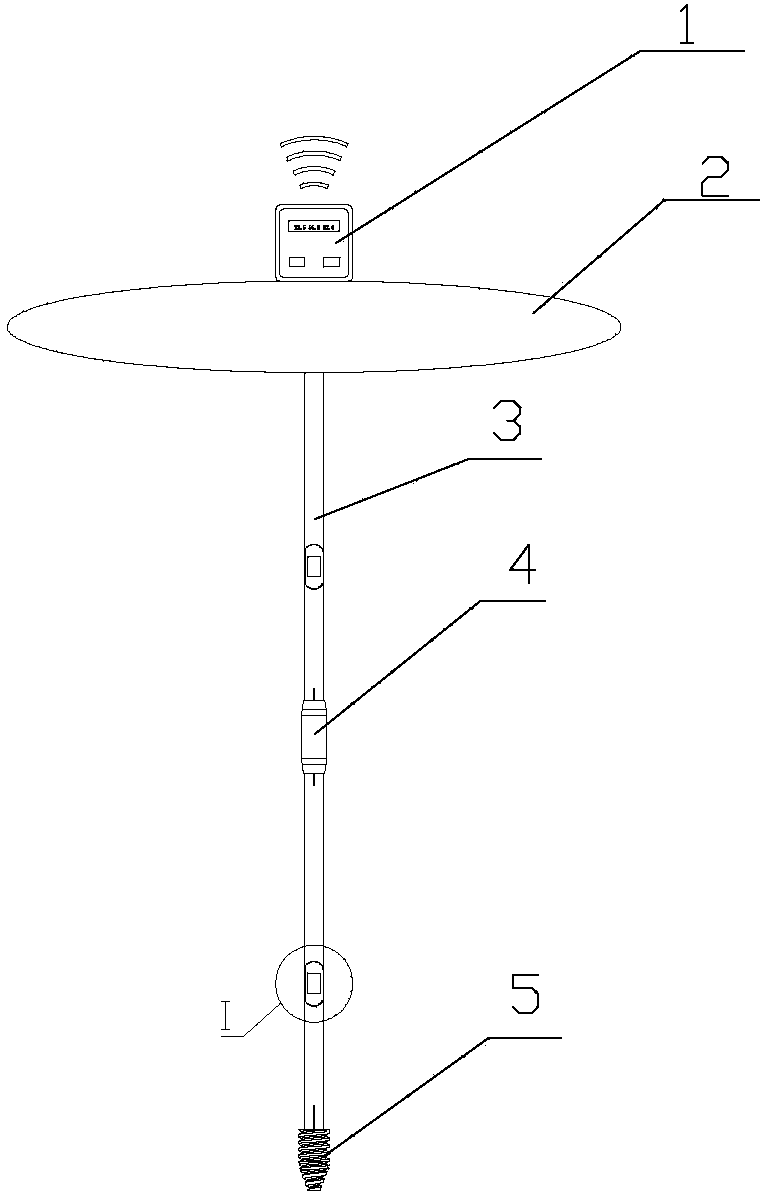
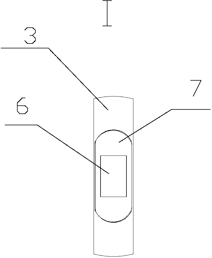
[0024] Such as figure 1 and 2 As shown, the present invention includes a hollow cylindrical rod body 3 . A temperature sensing device is provided on the rod body 3 . The device includes a thermal conductor 6 embedded in the rod body 3 and a temperature sensor placed in the rod body 3 and in close contact with the thermal conductor 6 . The thermal conductor 6 is made of copper with high thermal conductivity. Between the rod body 3 and the heat conductor 6 is provided a heat insulating layer 7 made of extremely low thermal conductivity flame-retardant nylon. Threads and electrical connectors are provided at both ends of the rod body 3 , and the two rod bodies can be cascaded and electrically communicated through the bolt fastening device 4 . A wireless transceiver control terminal 1 electrically connected to the rod body is installed on the top of th...


PUM


Abstract

The invention relates to a temperature measuring rod which comprises hollow cylindrical rod bodies and a wireless transceiving control terminal, wherein the wireless transceiving control terminal is fixed at one end of one rod body and electrically connected with the rod body; a temperature induction device is arranged on one rod body; connecting threads and an electrical connector are arranged at two ends of the rod body, and connection and electrical communication between the rod bodies can be realized through a hard bolt fastening device. The temperature measuring rod is simple in structure and convenient to operate; three-dimensional distributed temperature measurement and remote control of a measured object are realized through multi-rod cascading and wireless transceiving control, and the measurement accuracy and the work efficiency are improved; and simultaneously, a drill and a floating carrier are supplemented, so that temperature measurement of different materials is realized, the requirements of different production fields are met, and the field application is more flexible, efficient and comprehensive.

Description

technical field [0001] The invention relates to a temperature measuring device, in particular to a temperature measuring rod. Background technique [0002] At present, in the production fields such as fishery or coal storage, the commonly used temperature measurement methods and their defects are mainly as follows: [0003] 1. Manually use traditional thermometers or electronic thermometer probes to directly collect water temperature on the surface of the water body or at a certain depth. The disadvantages of this technology are: large measurement workload, low efficiency, poor effectiveness, etc., it is impossible to distinguish the temperature information of different water layers, and it is impossible to grasp the law of water temperature changes in time. [0004] 2. Measure the surface temperature of the water body through the floating wireless thermometer and send it back. The disadvantages are: it can only measure the temperature of the surface layer of the water bod...

Claims


Application Information

Patent Timeline
IPC IPC(8): G01K13/02G01K13/10
Inventor 韩华韩奎
Owner NANJING LUOLIAN MEASUREMENT & CONTROL TECH
Learn More