
Tool replacing device for tail end of space robot

A space robot and tool replacement technology, applied in the direction of tools, manufacturing tools, manipulators, etc., can solve the problems such as the inability to lock the butt joints, the inability to realize the power output, the inability to realize the large tolerance capture of the replacement tool and the standard interface, etc. The effect of installation and maintenance

Active Publication Date: 2013-11-13
HARBIN INST OF TECH
View PDF11 Cites 15 Cited by
  • Summary
  • Abstract
  • Description
  • Claims
  • Application Information

AI Technical Summary

Problems solved by technology

[0005] The purpose of the present invention is to solve the problem that existing terminal replacement devices for space robots cannot lock butt joints at the same time of capture, cannot realize large-tolerance capture of replacement tools and standard interfaces under error conditions, and cannot realize capture of standard interfaces. The power output is to meet the installation and maintenance problems of the docking target, and then provide a tool replacement device for the end of the space robot

Method used

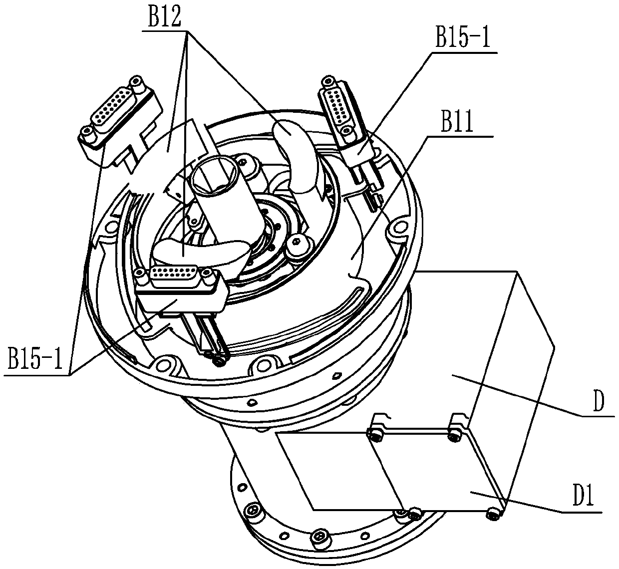

Image

  • Tool replacing device for tail end of space robot
  • Tool replacing device for tail end of space robot
  • Tool replacing device for tail end of space robot

Examples


specific Embodiment approach 1

[0015] Specific implementation mode one: combine Figure 1-Figure 6 Describe this embodiment, a tool replacement device for the end of a space robot in this embodiment includes a base A1, a connecting sleeve A2, a capture locking and electrical pushing system B and a drive mechanism C; the base A1 is equipped with a connecting sleeve A2;

[0016] The capture locking and electrical appliance pushing system B includes an interface sleeve B1, a docking sleeve B2, a first motor B5, a first harmonic drive reducer B7, a rotating body B11, three sets of capture claws B12, three sets of contact switches B14 and Three sets of electrical relay mechanism B15;

[0017] The lower end surface of the interface sleeve B1 is connected with the connection sleeve A2, and the upper end surface of the interface sleeve B1 is connected with the docking sleeve B2; the connection sleeve A2 is provided with the first motor B5, and the interface sleeve B1 is provided with the first harmonic drive reduce...

specific Embodiment approach 2

[0025] Specific implementation mode two: combination figure 1 and figure 2 To describe this embodiment, the connecting sleeve A2 in this embodiment is a cylindrical connecting sleeve. Such setting is convenient to use and meets design requirements and actual needs. Others are the same as in the first embodiment.

specific Embodiment approach 3

[0026] Specific implementation mode three: combination figure 2 To illustrate this embodiment, the interface sleeve B1 in this embodiment is a tapered cylindrical interface sleeve, the butt joint sleeve B2 is a cylindrical butt joint sleeve, the small diameter end of the interface sleeve B1 is connected to the connection sleeve A2, and the large diameter end of the interface sleeve B1 The diameter end is connected with the butt sleeve B2. Such setting is convenient to use and meets design requirements and actual needs. Others are the same as in the second embodiment.


PUM


Abstract

The invention relates to a tool replacing device for a tail end of a space robot, which relates to a tool replacing device, and aims at solving the problems of the existing tail end replacing device for the space robot that a butt connecting piece cannot be locked while being captured, the big tolerance capturing cannot be realized under the condition that an error exists between the replacing tool and a standard interface, the power output cannot be realized after the standard interface is captured, and the installation and maintenance of a butt-connecting target cannot be satisfied. The tool replacing device comprises a base, a connecting sleeve, a capturing locking and electric appliance pushing system and a drive mechanism; the lower end surface of an interface sleeve is connected with the connecting sleeve, and the upper end surface of the interface sleeve is connected with a butt-connecting sleeve; a first motor is arranged inside the connecting sleeve, and a first harmonic transmission reducer and a rotary body are arranged inside the interface sleeve; a transmission shaft of the first motor is connected with a first wave generator; the drive mechanism comprises a second motor, a second harmonic transmission reducer and a socket spanner, and a rotating shaft of the second motor is connected with a second wave generator. The tool replacing device is used for the space robot.

Description

technical field [0001] The invention relates to a tool changing device, in particular to a tool changing device used at the end of a space robot. Background technique [0002] Some major successes in space development over the past two decades have underscored the importance of on-orbit maintenance. As space developers, our challenges go beyond simply launching complex spacecraft systems. The demand we are facing is how to fully develop the launched spacecraft system to build a large organizational structure for new scientific research and provide reliable and cost-effective support for the next step of space development. Due to the complexity and diversity of the space environment and the high risk of extravehicular activities, all countries have accelerated the research of space robot technology. The replacement device for the end of the space manipulator, which can handle a variety of different loads, has become one of the key technologies in this field. [0003] At pr...

Claims


Application Information

Patent Timeline
IPC IPC(8): B25J15/00B64G4/00
Inventor 刘宏曹宝石孙奎谢宗武任利学
Owner HARBIN INST OF TECH
Learn More