
System and method for camera control in a surveillance system

A camera and video technology, applied in the parts of TV systems, closed-circuit TV systems, TVs, etc., can solve problems such as inability to perform image analysis

Active Publication Date: 2013-10-30
INTERGRAPH
View PDF4 Cites 9 Cited by
  • Summary
  • Abstract
  • Description
  • Claims
  • Application Information

AI Technical Summary

Problems solved by technology

The disadvantage of this approach is that image analysis cannot be performed unless the object is within the camera's field of view

Method used


Image

  • System and method for camera control in a surveillance system
  • System and method for camera control in a surveillance system
  • System and method for camera control in a surveillance system

Examples


Embodiment approach

[0147] Exemplary embodiments of the present invention are not limited to the use of cameras characterized by pan, zoom, and tilt coordinates (eg, pan, zoom, and tilt cameras). For example, the exemplary embodiments of the present invention may also be used with fixed cameras or other cameras with a limited range of motion. In fact, the calibration and differentiation methods described above can be similarly applied to fixed cameras. In addition, according to an exemplary embodiment of the present invention, the visual frustum of a fixed camera may also change as it zooms. The different embodiments of the invention can also be applied to other types of cameras, for example cameras whose tilt orientation cannot be adjusted.

[0148] It should be noted that terms such as "system," "processor," "server," "input device," "display device," "communication network," and "database" are used herein to describe devices in the manner described, but is not to be construed as limiting the...


PUM


Abstract

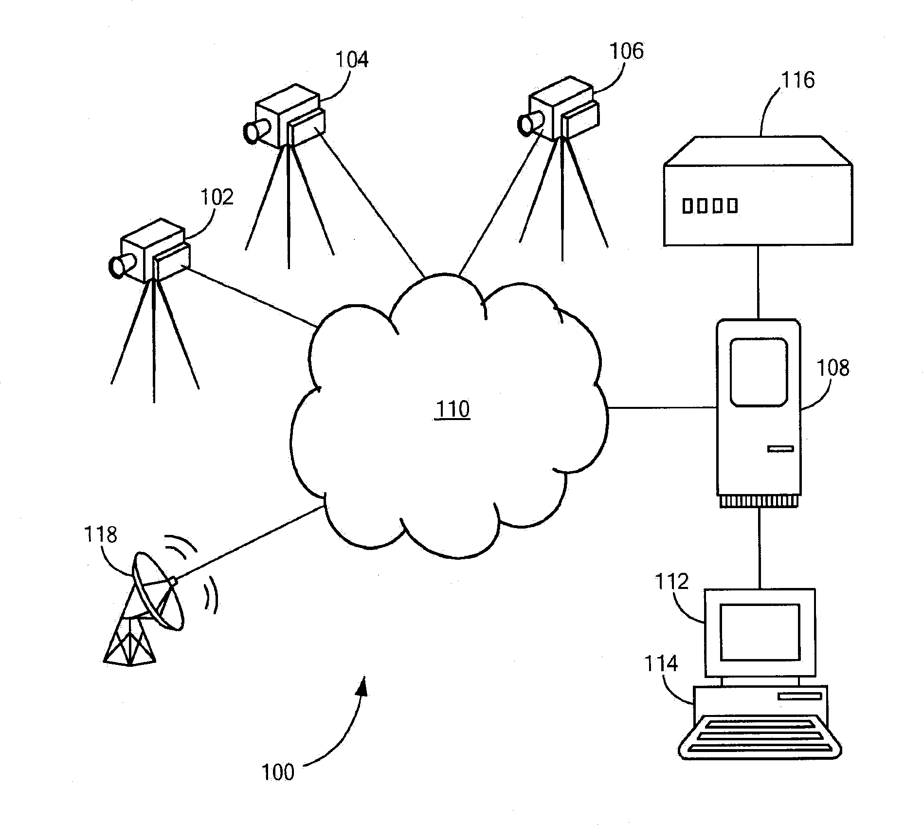
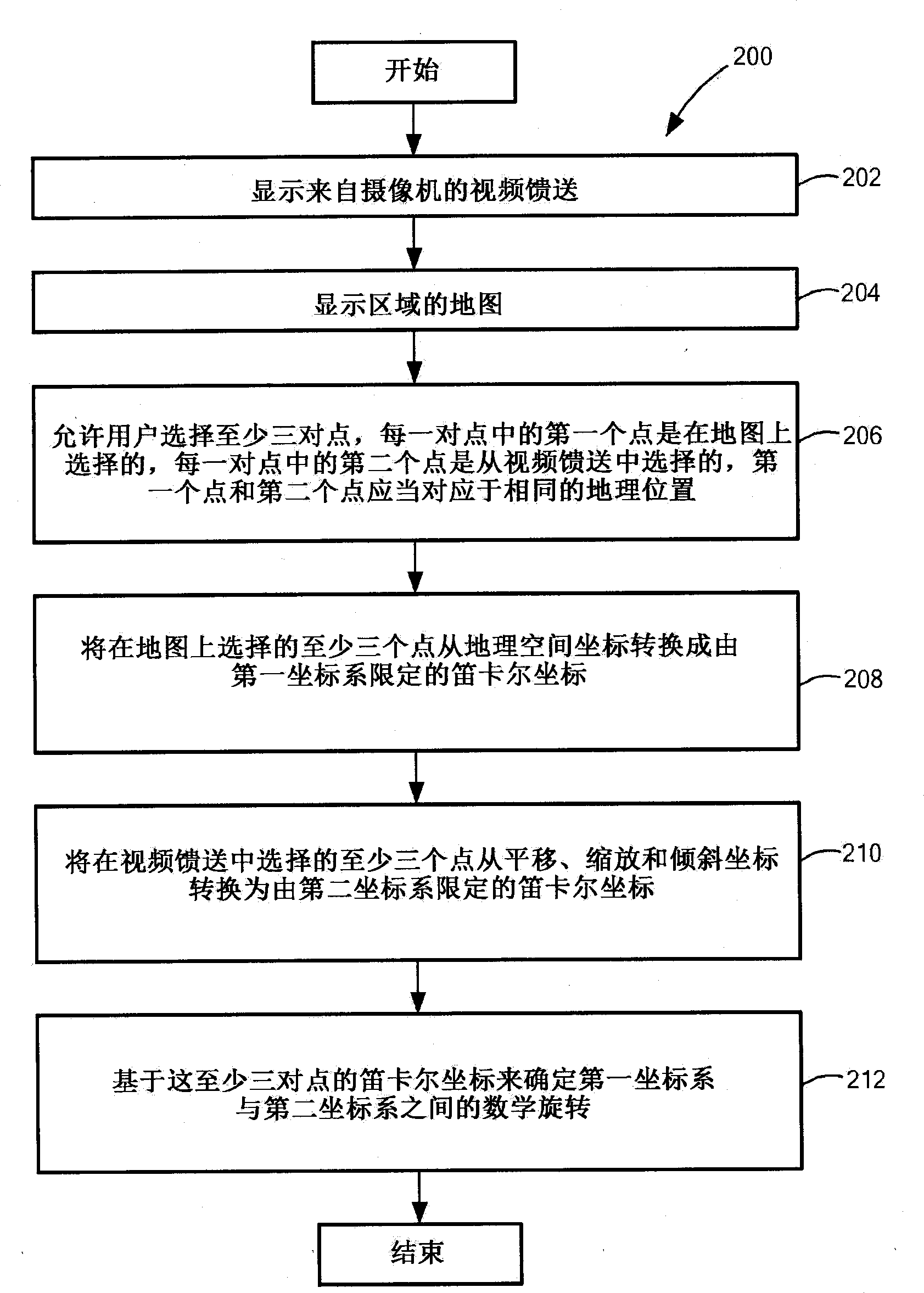
A method and a system for calibrating a camera in a surveillance system. The method and system use a mathematical rotation between a first coordinate system and a second coordinate system in order to calibrate a camera with a map of an area. In some embodiments, the calibration can be used to control the camera and / or to display a view cone on the map.

Description

technical field [0001] The invention relates to a camera control method, in particular to a camera control method in a surveillance system. Background technique [0002] Surveillance systems use cameras to monitor areas of interest. The camera produces a video feed that can be displayed to the user. In this way, the user can remotely observe the area of ​​interest. In some cases, the cameras in the surveillance system are fixed and the user cannot change their field of view. In other cases, however, the cameras and their fields of view may be adjusted through user controls. Typically, such control is accomplished using a manual control, such as a joystick. Thus, if the video feed includes a moving object, the user manually controls the camera to follow the moving object. Such manual control of the camera is not very efficient, especially if the user needs to capture and / or respond to the moving object within a limited time period. These problems are further compounded ...

Claims


Application Information

Patent Timeline
IPC IPC(8): H04N7/18
CPCH04N7/181H04N5/232H04N23/635H04N23/695H04N7/18
Inventor A·D·埃斯蒂斯J·E·弗雷德里克
Owner INTERGRAPH
Learn More