System for converting thermal energy to mechanical energy in a vehicle

A heat energy conversion and mechanical energy technology, applied in mechanical equipment, charging system, engine cooling, etc., can solve problems such as difficult to adjust air-cooled condensers

Inactive Publication Date: 2013-10-30
SCANIA CV AB
View PDF9 Cites 7 Cited by
  • Summary
  • Abstract
  • Description
  • Claims
  • Application Information

AI Technical Summary

Problems solved by technology

Since most of these parameters depend on the state of the surrounding ambient air, it is difficult to adjust the cooling in air-cooled condensers so that the medium is cooled to the desired temperature

Method used


Image

  • System for converting thermal energy to mechanical energy in a vehicle

Examples


Embodiment Construction

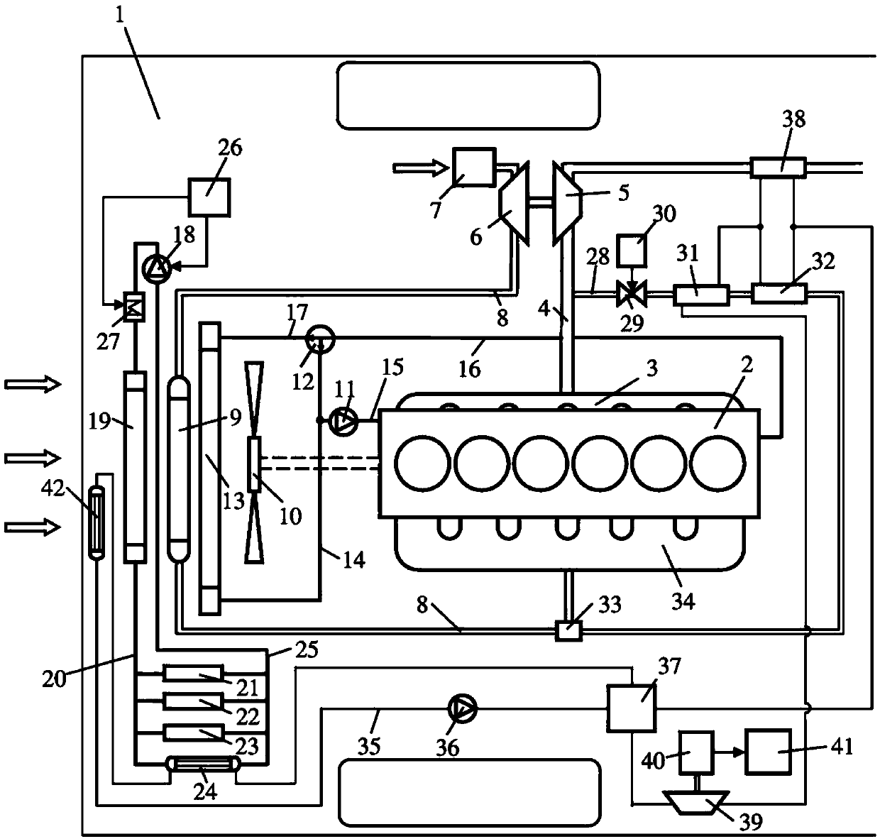
[0015] figure 1 A vehicle 1 powered by a supercharged internal combustion engine 2 is shown. The vehicle 1 may be a heavy duty vehicle powered by a supercharged diesel engine. Exhaust gases from cylinders of the engine 2 are led to an exhaust line 4 via an exhaust manifold 3 . The exhaust gas in the discharge line 4 which is to be at a pressure above atmospheric is led to the turbine 5 of the turbo unit. Thus, the turbine 5 is provided with a driving force which is transmitted to the compressor 6 via the connection. The compressor 6 then compresses the air which is led into the inlet line 8 via the filter 7 . A charge air cooler 9 is arranged in the supply line 8 . The charge air cooler 9 is positioned in the area at the front of the vehicle 1 . The purpose of the charge air cooler 9 is to cool the compressed air which is led to the engine 2 . The compressed air is cooled in the charge air cooler 9 by the air being pushed through the charge air cooler 9 by the airflow ca...


PUM


Abstract

A system for converting thermal energy to mechanical energy in a vehicle: A line circuit (35), a pump (36) for recirculating a medium in the line circuit, at least one evaporator (31, 32, 38) in which the medium is caused to absorb thermal energy from a heat source (4, 28) so that the medium becomes vaporised, a turbine (39) driven by the vaporised medium in order to generate mechanical energy, followed by a condenser arrangement (24, 42) in which the medium is caused to give off thermal energy so that it condenses. The condenser arrangement includes a first condenser (24) in which the medium gives off thermal energy to coolant which circulates in a cooling circuit, and a second condenser (42) downstream of the first condenser (24) with respect to the medium's direction of flow in the line circuit (35) and in which the medium gives off thermal energy to air at the temperature of the surroundings.

Description

technical field [0001] The invention relates to a system for converting thermal energy into mechanical energy in a vehicle according to the preamble of claim 1 . Background technique [0002] When fuel is burned in an internal combustion engine, chemical energy is converted into mechanical energy. A considerable portion of the chemical energy is not converted into mechanical energy, but into thermal energy which is released into the surrounding environment in several ways. An example of this is the heat energy in the exhaust that is emitted into the surrounding air. Another example is thermal energy cooled from various heat media in a vehicle. An example of such a heat medium is a coolant in a cooling system that cools an internal combustion engine. Here, the coolant is usually cooled in a radiator located at the front of the vehicle. Many internal combustion engines are supercharged. The charge air is usually cooled in at least one charge air cooler before being introd...

Claims


Application Information

Patent Timeline
Patent Type & Authority Applications(China)
IPC IPC(8): F02G5/02F01N5/02F01P9/04F02M25/07
CPCF01N2240/02F01N5/02F01K23/065F01K23/06F02M25/074Y02T10/121F01P9/00Y02T10/16F02M26/35Y02T10/12F01P9/04F02G5/02F02M26/24
Inventor Z·卡多斯D·雅恩斯
Owner SCANIA CV AB
Why Eureka
Try Eureka