
Method for sheet transfer and die cutting with gripper transport system

A conveying system and sheet technology, applied in the direction of sending objects, transportation and packaging, object supply, etc., to achieve the effect of precise orientation of sheets and high registration quality

Active Publication Date: 2013-10-30
MASTERWORK GROUP CO LTD
View PDF8 Cites 2 Cited by
  • Summary
  • Abstract
  • Description
  • Claims
  • Application Information

AI Technical Summary

Problems solved by technology

[0006] This short time window is disadvantageous for precise sheet orientation

Method used


Image

  • Method for sheet transfer and die cutting with gripper transport system
  • Method for sheet transfer and die cutting with gripper transport system
  • Method for sheet transfer and die cutting with gripper transport system

Examples


Embodiment Construction

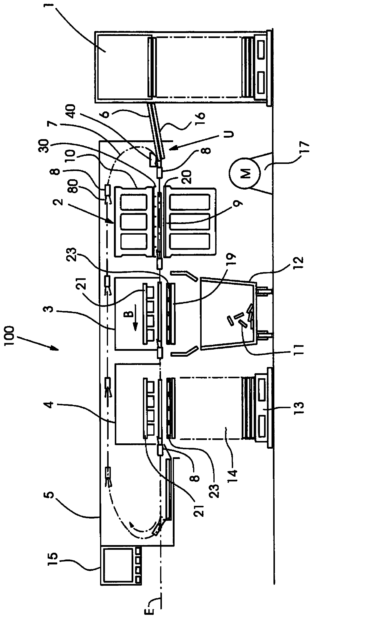
[0025] figure 1 The schematic design of a sheet die-cutting and embossing machine 100 for die-cutting, stripping, separating useful parts and depositing sheets made of paper, cardboard, plastics and the like is shown in FIG. The die-cutting and embossing machine 100 comprises a feeder 1, a die-cutting station 2, a stripping station 3 and a receiver 4 with a placement and useful part separation station 20, which consist of a common machine housing 5 carries and surrounds and is driven by the main driver 17. The processing stations 2 , 3 , 4 are accessible from one side, the so-called operator side; the drive train of the sheet-cutting and embossing machine 100 is located on the opposite side, the so-called drive side. A corresponding machine control device 15 controls the processes within the die-cutter 100 .

[0026] The sheets 6 are separated from a stack by means of a feeder 1 via so-called suction heads 18 , fed to the sheet conveyor system 7 at the sheet transfer point U...


PUM


Abstract

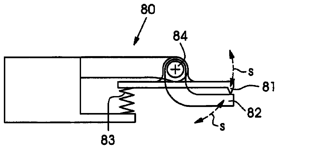
The invention relates to a method for transferring sheets from a sheet feeder to a sheet conveying system. The sheets and a gripper vehicle enter into a sheet transfer part in a non-collision manner. The invention further relates to a sheet die cutting and / or coining machine including a sheet feeder, at least one processing station, and a sheet conveying system. The sheet conveying system is provided with a batch-type revolving gripper vehicle for conveying the sheets to pass through the sheet die cutting and / or coining machine on a sheet operation plane, and the gripper vehicle is provided with a plurality of grippers for gripping the sheets, and the sheets are transferred from the feeder to the sheet conveying system at the sheet transferring part. According to the invention, each gripper is provided with a gripper seat and a gripper rod, and the gripper seat or the gripper rod is capable of pivoting or sliding to the part under the sheet operation plane to enable the corresponding gripper to be opened, so that the grippers can be further opened and pass through the sheet operation plane early.

Description

technical field [0001] The invention relates to a method for transferring sheets as claimed in claim 1 and to a sheet cutting and / or embossing machine as described in the preamble of claims 3 or 6 . Background technique [0002] Cutting with a cutting die of a closed geometry, which can be round, oval or polygonal and any kind of irregular shape, is called "die cutting". Processes performed in post-press processing such as die-cutting with punches, corner cutting and index die-cutting also belong to this field. Die-cutting is carried out against a die-cutting block or against an impression, partly also a shearing process. Packaging materials made of paper, cardboard, cardboard or corrugated are mainly die-cut in sheet format. It is also possible to additionally apply stripe lines or arches in the useful part during the die-cutting process. This complex process makes it absolutely necessary that the sheets are die-cut individually. Since the final product involves packagi...

Claims


Application Information

Patent Timeline
IPC IPC(8): B65H5/04B65H5/08B65H5/14
CPCB65H5/14B65H29/044B65H2801/42B65H5/085
Inventor D·埃尔巴A·米勒
Owner MASTERWORK GROUP CO LTD
Learn More