Container with cover
A container and lid technology, applied in the directions of lids, caps, heat-insulating utensils, etc., can solve the problems of detrimental appearance and non-uniformity, and achieve the effects of improving waterproofness, reducing clamping force and improving appearance.
- Summary
- Abstract
- Description
- Claims
- Application Information
AI Technical Summary
Problems solved by technology
Method used
Image

Examples
Embodiment 1
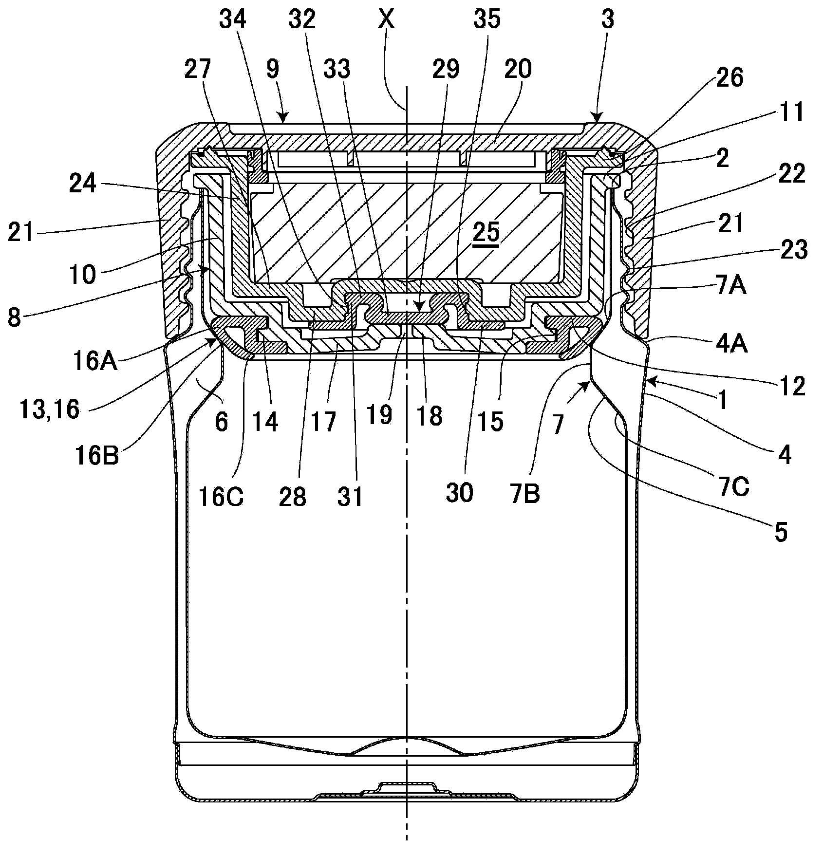
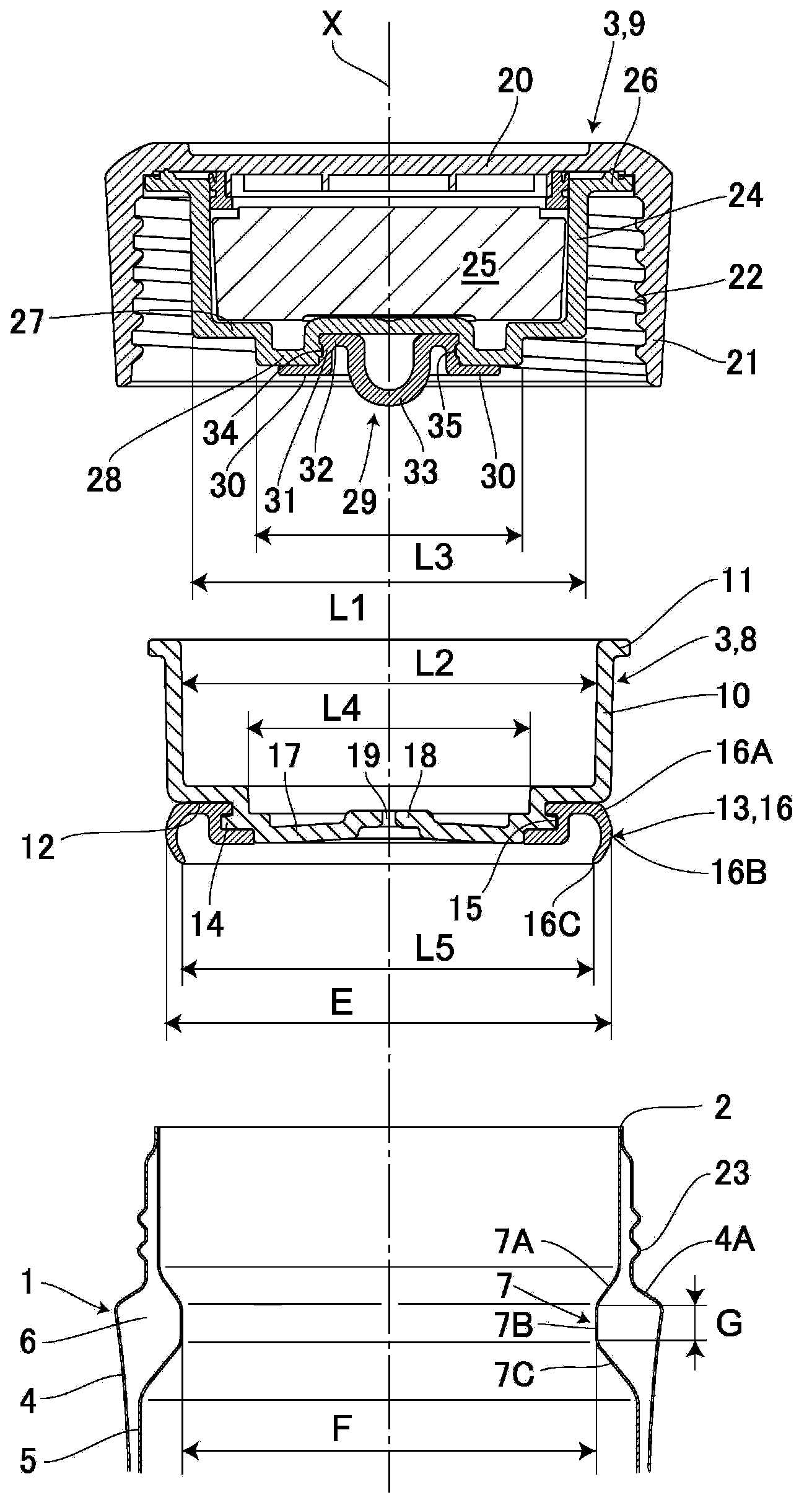
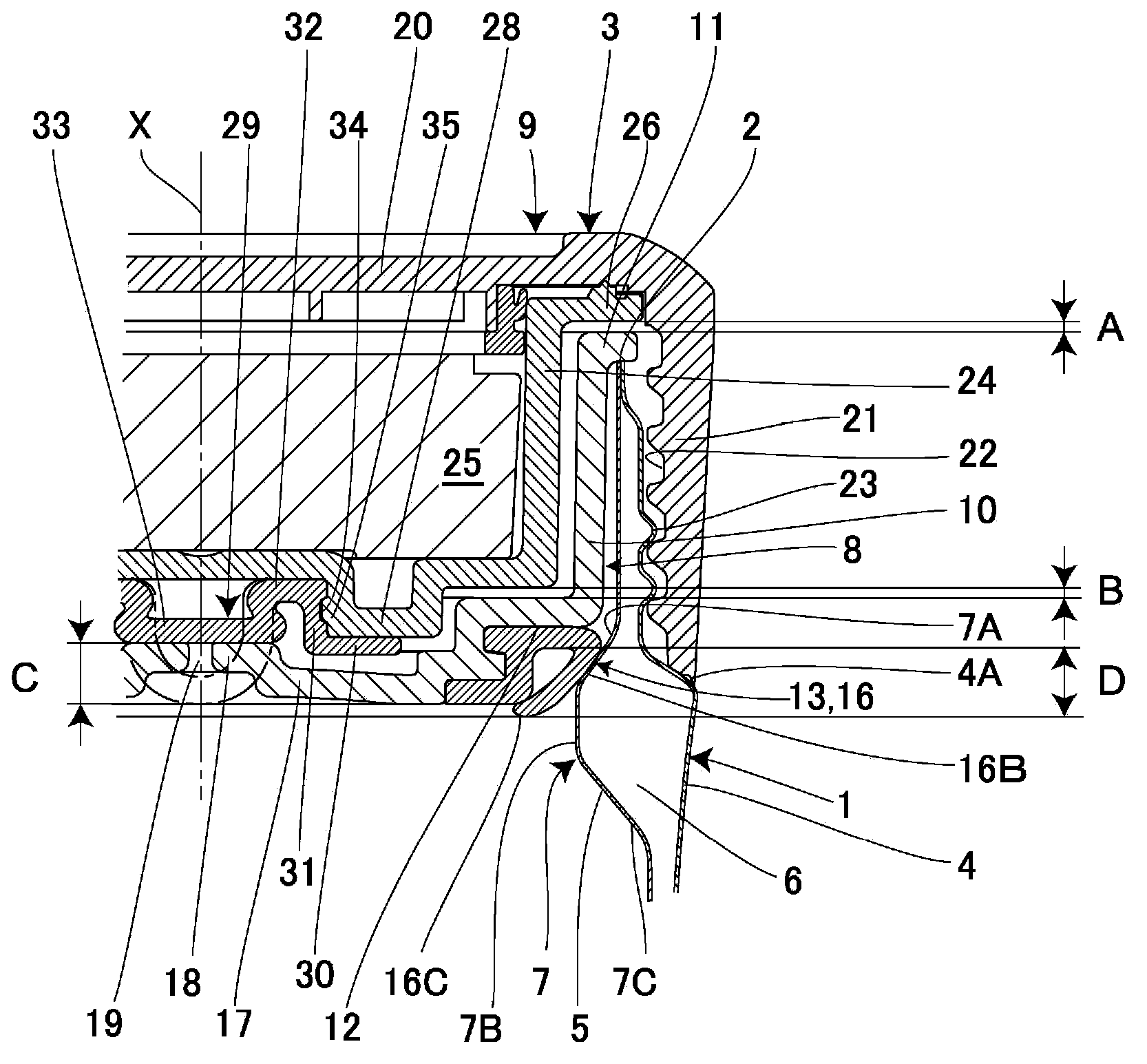
[0030] Figure 1~6 Example 1 is shown. Among them, the cover 3 is detachably installed on the upper opening 2 of the heat-retaining container main body 1 made of metal or resin, which is a container. The thermal insulation container main body 1 is provided with a stainless steel bottomed inner cylinder 5 on the inner side of a stainless steel bottomed outer cylinder 4, and joins the upper edges of these outer cylinders 4 and inner cylinders 5 to form a wide-mouthed upper opening 2. . Here, a vacuum layer 6 as a heat insulating layer is provided between the outer cylinder 4 and the inner cylinder 5, thereby forming a heat insulating double-layer container. In addition, a protrusion 7 is provided slightly below the upper opening 2 of the inner cylinder 5, and the protrusion 7 is formed in a segmental shape facing inward.
[0031] Here, the protrusion 7 includes: a first inclined portion 7A whose diameter decreases from above to downward; a vertical surface portion 7B extendin...
Embodiment 2
[0059] Figure 7 ~ Figure 8In order to show the second embodiment, the parts that are the same as those in the above-mentioned first embodiment are denoted by the same symbols, and the detailed description of the parts will be omitted. Regarding the packing 40 formed on the outer peripheral portion of the waterproof packing 13 of this embodiment, it is formed in the following shape. That is, the diameter cross-section extends substantially linearly from the upper portion 40A to the middle portion 40B, and the middle slope portion 40B is the largest diameter portion of the packing 40 . Furthermore, the cross-sectional diameter thereof decreases substantially linearly from the middle portion 40B to the lower portion 40C, thereby forming a lip shape in which the lower portion 40C is opened.
[0060] By forming the packing 40 in the above-mentioned configuration, the waterproof packing 13 of the inner cover 8 is pressed from above in the direction of the axis X by the air hole cl...
Embodiment 3
[0063] Figure 9 ~ Figure 10 In order to show the third embodiment, the parts that are the same as those in the above-mentioned first embodiment are denoted by the same symbols, and the detailed description of the parts is omitted. The packing 50 formed on the outer peripheral portion of the waterproof packing 13 of this embodiment is formed in the shape of a tongue protruding outward in the circumferential direction. Here, the outer diameter E of the packing portion is defined as the outer diameter of the tip portion of the packing portion 50 .
[0064] With the packing 50 having the above configuration, the waterproof packing 13 of the inner cover 8 is pressed from above in the direction of the axis X via the air hole closing packing 33 provided on the outer cover 9, and the packing 50 is elastically deformed as follows. . That is, along the first inclined portion 7A of the protrusion 7 , the filler 50 is elastically deformed in a diameter-reducing direction so as to be ro...
PUM
 Abstract
Description
Claims
Application Information
 - R&D
- Intellectual Property
- Life Sciences
- Materials
- Tech Scout
- Unparalleled Data Quality
- Higher Quality Content
- 60% Fewer Hallucinations
Browse by: Latest US Patents, China's latest patents, Technical Efficacy Thesaurus, Application Domain, Technology Topic, Popular Technical Reports.
© 2025 PatSnap. All rights reserved.Legal|Privacy policy|Modern Slavery Act Transparency Statement|Sitemap|About US| Contact US: help@patsnap.com